[0008]The primary object of present invention is to provide a transversal suspension rod for a ceiling fan, wherein two ends of an extensible tube rack set are provided with hidden claws, and an interior of the extensible tube rack set is provide with an automatic elongation structure, so as to increase a safety of usage, and a convenience in installation.
[0009]Another object of the present invention is to provide a transversal suspension rod for a ceiling fan, wherein a wiring box is made by a metallic box and a plastic box which are pressed into one body with plastic rivets. An interior of the plastic box is integrally formed with a plurality of fixing holes and a plurality of side openings; whereas a center of the plastic box is surrounded by wire-clipping slots in a sawtooth shape, so as to provide a convenience to a user.
[0010]Still another object of the present invention is to provide a transversal suspension rod for a ceiling fan, wherein an opening place of a fixing hole of the plastic box of wiring box used for locking with an assembly member is provided with an inverted hook, so as to decrease a difficulty in assembling with the assembly member.
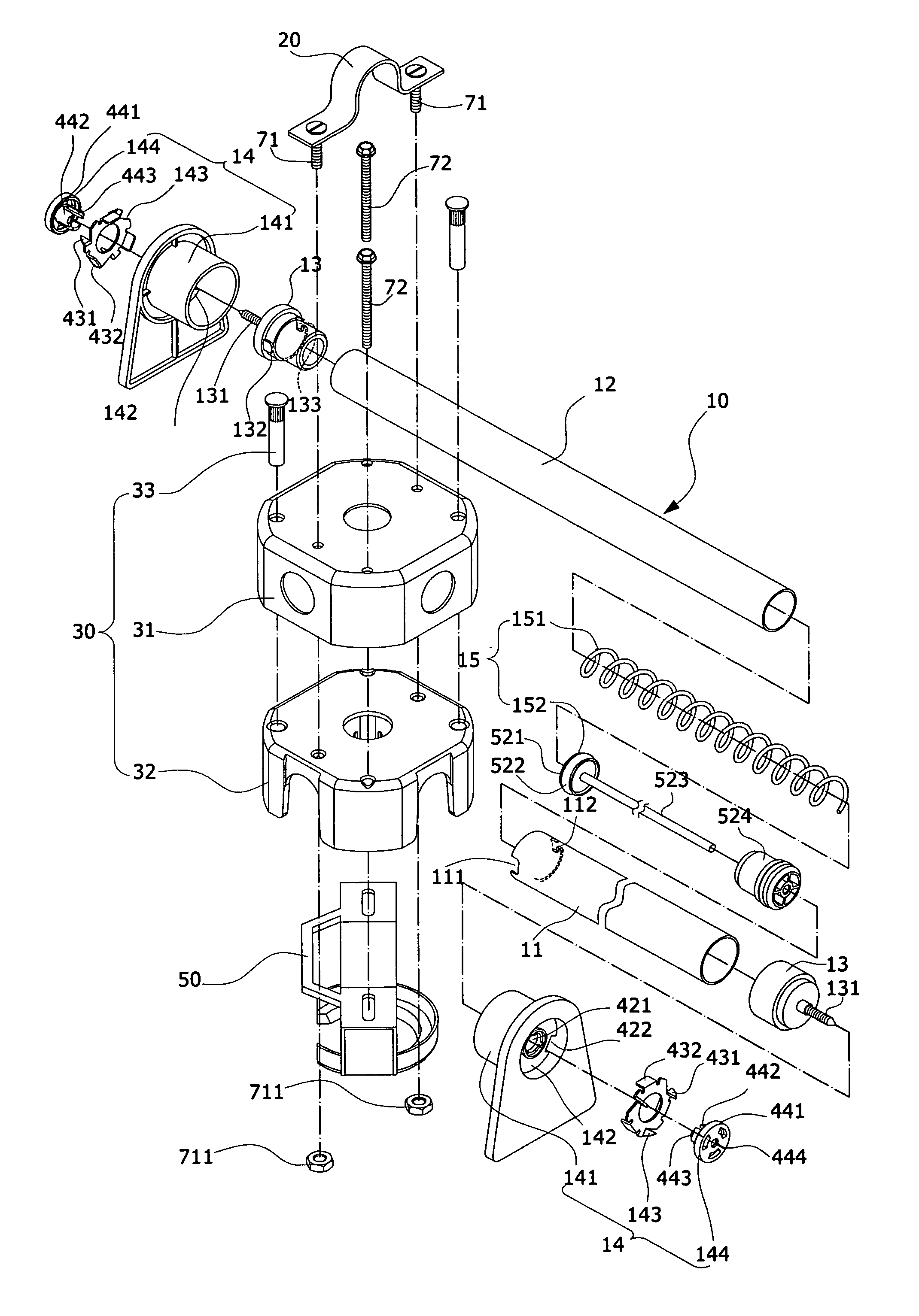
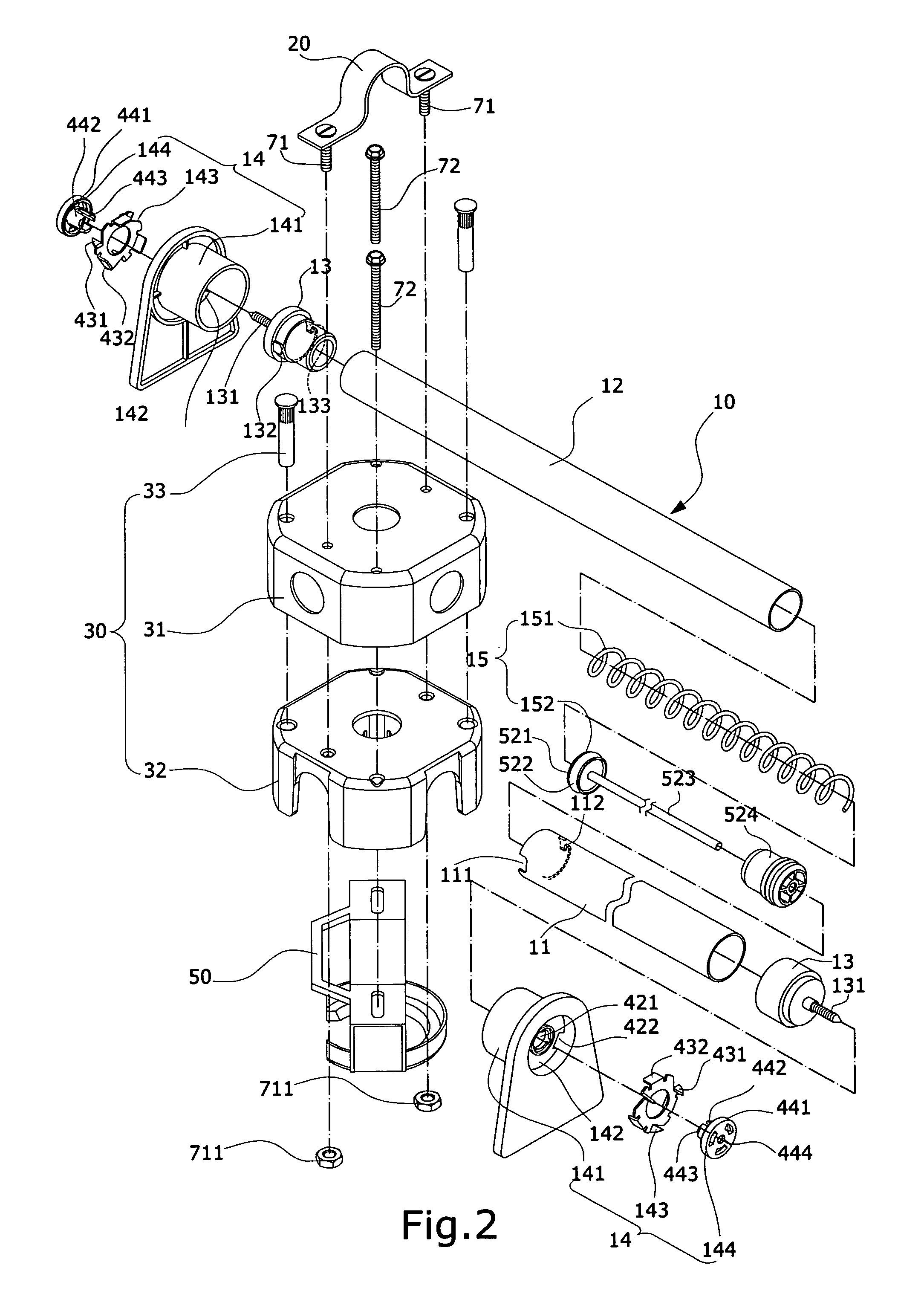
[0011]In order to achieve the aforementioned objects, interiors of the positioning plates sheathed at two ends of the extensible tube rack set are provided with the hidden claws, respectively. The positioning plate is a triangular plate, above which is transversally located with a round tube, and an interior of which is provided with a baffle. The positioning plate can be sheathed at an exterior of the corresponding locking member with an end of the round tube, and an interior of the other end of round tube is orderly provided with a claw-piece and a plug. A center of the aforementioned baffle is provided with a round hole and a plurality of long holes at a rim of the round hole. The claw-piece is in a ring-shape, a front end of which is provided with a plurality of thorns, and a rear end of which is provided with a plurality of abutting portions corresponding to the long holes of baffle. An end of the plug is a disk of a larger
diameter, whereas the other end is a cylinder of a smaller
diameter. The cylinder is flexible, can be transfixed into the round hole at the center of baffle, and its end part is formed outward with an inverted hook. A center of the plug is provided with a
small hole for protruding a screw of the locking member. In assembling, the claw-piece is assembled into the round tube of positioning plate with the plug, and the abutting portions of claw-piece are transfixed into the baffle to be extended out by a pushing of the locking member, and can be snapped into beams by a pressure resulting from a rotation of the screws of locking members into the beams, such that the transversal suspension rod can be firmly supported and assembled.
[0012]According to the aforementioned structures, an automatic elongation structure is located between the locking members being fixed on the outer tube and inner tube of extensible tube rack set, respectively. The automatic elongation structure includes a spring and a gliding rod. The gliding rod can be abutted on the locking member fixed at the outer tube end, by an elastic force released from the spring, such that the outer tube can be extended out automatically, to achieve an object of quick elongation. Moreover, a notch and a hook tip which is projected inward are located on the outer tube, at a place close to an end opening of the locking member fixed at the inner tube. The notch and the hook tip are opposite to a lump and an L-shape slot on the locking member fixed at the inner tube, respectively. When the notch of outer tube is locked with the lump, the locking member of inner tube can be driven by the outer tube so that the locking member is rotated into the beam, and a locking state is formed when the hook tip of outer tube is latched into the L-shape slot. On the other hand, when the outer tube is reversely rotated to release the hook tip from the L-shape slot, an unlocking state is formed to release the elastic force, thereby achieving an effect of automatically and quickly elongating the extensible tube rack set.
[0013]Furthermore, the wiring box of present invention is made by a metallic box and a plastic box which are pressed into one body with the plastic rivets. The interior of the plastic box is integrally formed with the plurality of fixing holes, and the plurality of side openings; whereas the center of plastic box is surrounded by the sawtooth-shape wire-clipping slots, so as to facilitate assembling and to reduce
working hours for manufacturing. On the other hand, the opening place of one fixing hole used for locking with the assembly member is provided with the elastic inverted hook which is projected inward, so as to decrease the difficulty in assembling with the assembly member.



