
Radio-frequency transmission arrangement for a magnetic resonance system

a magnetic resonance system and radio frequency transmission technology, applied in the direction of magnetic variable regulation, process and machine control, instruments, etc., can solve the problems of unwanted changes in the image intensity of the shown mr image, costly and time-consuming,

Inactive Publication Date: 2008-04-03
SIEMENS HEALTHCARE GMBH
View PDF23 Cites 5 Cited by
  • Summary
  • Abstract
  • Description
  • Claims
  • Application Information

AI Technical Summary

Benefits of technology

[0007] An object of the present invention is to provide a radio-frequency transmission arrangement with which different field distributions or, respectively, modes can be generated in a simple manner.
[0013] An advantage of the use of orthogonal modes is also that possible routine calibration tasks can be omitted in the installation of the antenna insert. These calibration tasks would be necessary in order to reduce interaction between the two transmission arrangements upon installation of the antenna insert and given use of the already-present whole-body antenna.
[0016] According to a further aspect of the invention, a method is provided for generation of a resulting B1 field of a magnetic resonance system by a radio-frequency transmission arrangement with a number of channels, with a first portion of the B1 field being generated by the single-channel whole-body antenna of the magnetic resonance system. A further second portion of the B1 field is generated by the antenna insert, such that the resulting B1 field is generated by the whole-body antenna and the antenna feed. As mentioned above, it is advantageous when the portion of the B1 field to be generated by the whole-body antenna orthogonally to the second portion of the B1 field generated by the antenna insert.

Problems solved by technology

Temporal and spatial fluctuations in the field strength of the excited B1 field lead to changes in the acquired MR signal, which leads to unwanted changes of the image intensity in the shown MR image.
This is very costly and time-intensive.

Method used


Image

  • Radio-frequency transmission arrangement for a magnetic resonance system
  • Radio-frequency transmission arrangement for a magnetic resonance system
  • Radio-frequency transmission arrangement for a magnetic resonance system

Examples


Embodiment Construction

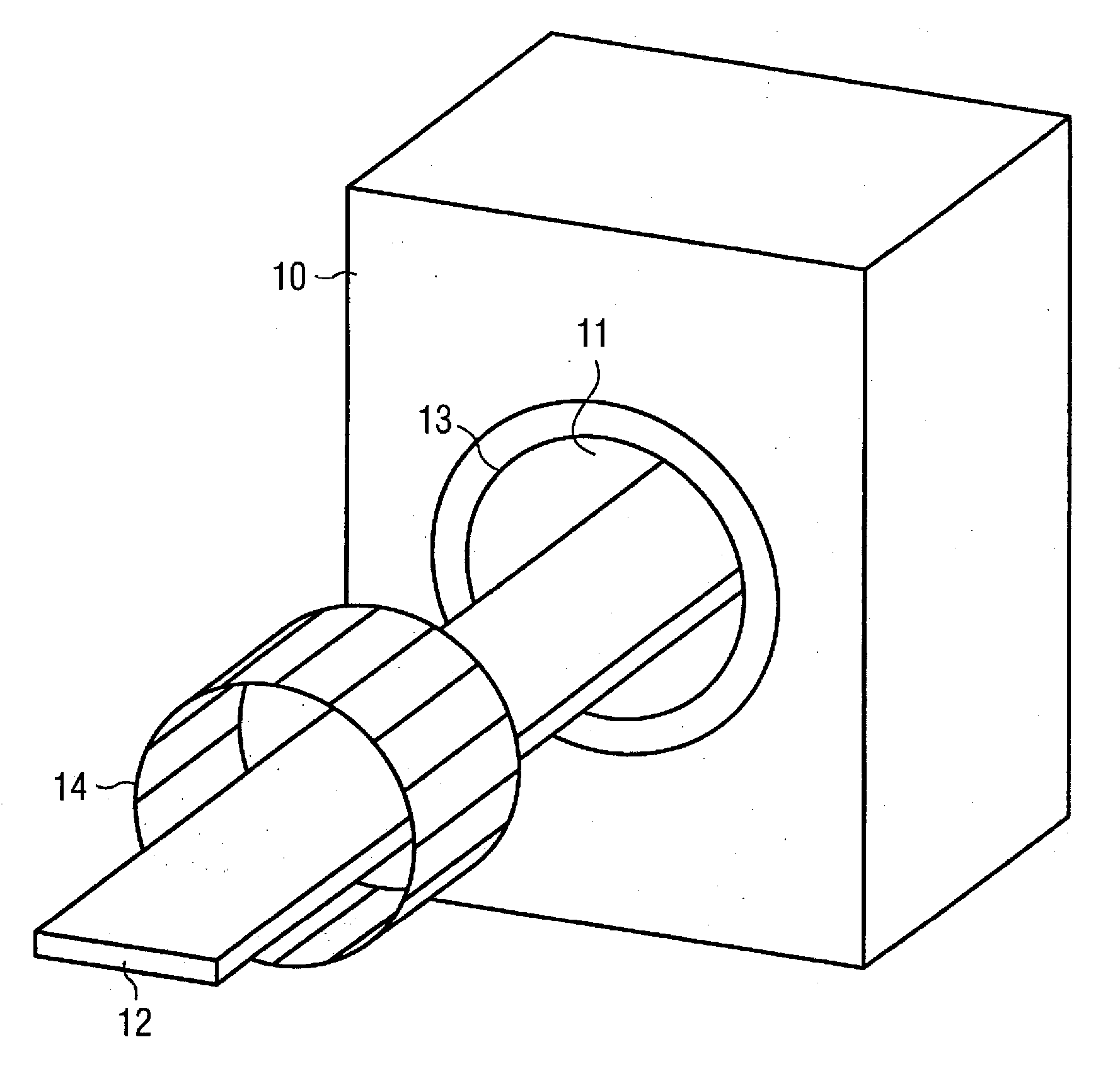
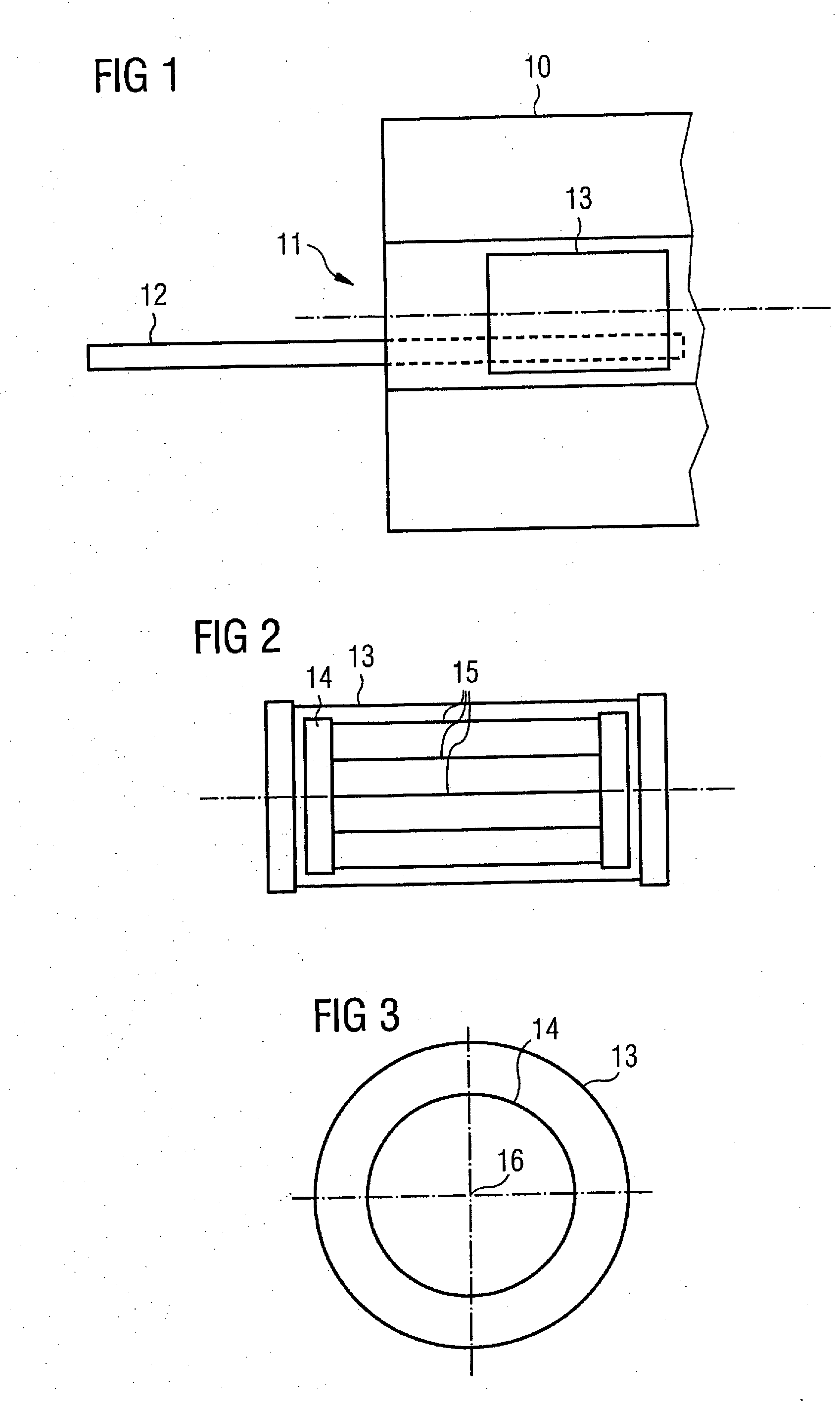
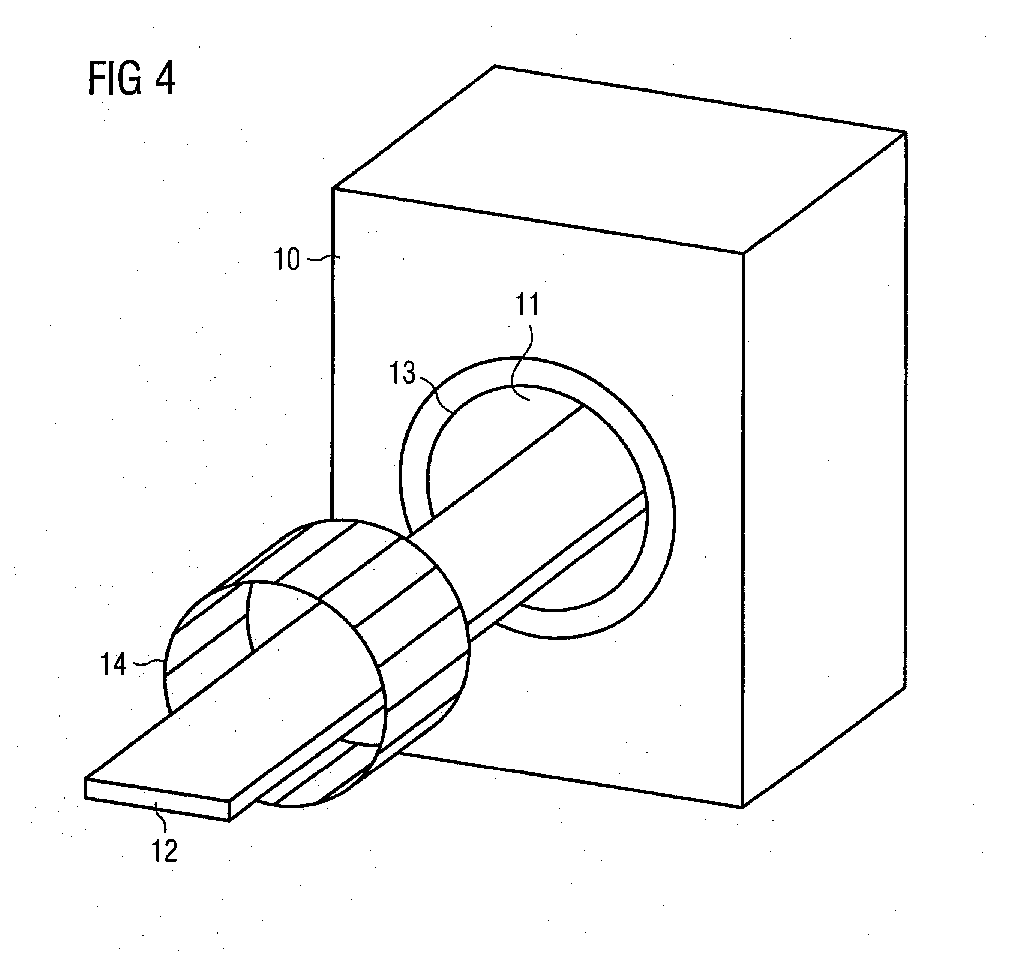
[0021] Schematically shown in FIG. 1 is a MR system 10 in a cross-section. As generally known, this MR system 10 has an opening 11 into which a patient table 12 with an examination person (not shown) lying thereon can be inserted. The functionality of the MR system is generally known and need not be explained in detail herein. Furthermore, in FIG. 1 a whole-body antenna 13 that is permanently integrated into the MR system, that generates a homogeneous B1 field in the examination subject to excite magnetization of the nuclear spins. In the present context, the term “whole-body antenna” means an antenna of the type typically installed in an MR system. This whole-body antenna can generate a homogeneous field distribution. If a multi-channel transmission arrangement should be generated in the MR system shown in FIG. 1, this whole-body antenna 13 would have to be exchanged. However, according to the invention it is possible to use this whole-body antenna 13 (which is also shown in FIG. 2...


PUM


Abstract

A radio-frequency transmission arrangement for an MR system for generation of a total B1 field which has a first antenna device that generates a first portion of the total B1 field and at least one antenna insert that generates a second portion of the total B1 field, such that the resulting B1 field is generated by the first antenna device and the at least one antenna insert.

Description

BACKGROUND OF THE INVENTION [0001] 1. Field of the Invention [0002] The present invention concerns a radio-frequency transmission arrangement for a magnetic resonance system for generation of a B1 field. [0003] 2. Description of the Prior Art [0004] Using magnetic resonance tomography it is possible to generate slice images of the human body in arbitrary planes by selected excitation of the magnetization of nuclear spins in examination subject located in an optimally homogeneous, static basic magnetic field (also designated as a B0 field). To excite the magnetization resulting from the nuclear spins, radio-frequency pulses are radiated into the examination subject with radio-frequency antenna. The electromagnetic flux density of these radio-frequency pulses is typically designated as a B1 field. Usually the specification of the radio-frequency pulses necessary for magnetic resonance excitation is provided digitally by control electronics as a sequence of complex numbers. These are s...

Claims


Application Information

Patent Timeline
Patent Type & Authority Applications(United States)
IPC IPC(8): G01R33/28
CPCG01R33/3415G01R33/34046
Inventor NISTLER, JUERGENSCHNELL, WILFRIED
Owner SIEMENS HEALTHCARE GMBH
Learn More