Display systems with spatial light modulators

Inactive Publication Date: 2008-04-03
TEXAS INSTR INC
View PDF9 Cites 39 Cited by
  • Summary
  • Abstract
  • Description
  • Claims
  • Application Information

AI Technical Summary

Benefits of technology

[0007]As an object of the invention, a projection system is disclosed. The system comprises: a light source providing a light beam, a lens, an optical diffuser, and a spatial light modulator disposed along a propagation path

Problems solved by technology

Using solid state light source in display systems, however, is also challenging.
One of the challenges is a uniform image shape that matches the shape of the spatial light modulator surface.
Another challenge is to reduce unwanted artifacts, such as the visual laser coherent speckle in the image.
Though conventional illu

Method used


Image

  • Display systems with spatial light modulators
  • Display systems with spatial light modulators
  • Display systems with spatial light modulators

Examples


Embodiment Construction

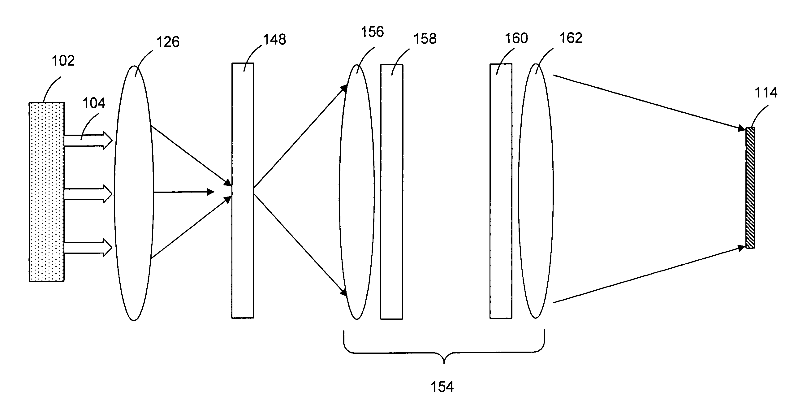
[0027]This invention discloses an illumination system used in projection systems that employ spatial light modulators. For providing uniform illumination light with a desired illumination field, the illumination system employs an optical diffuser.

[0028]In the following, the present invention will be discussed with reference to particular examples wherein the light source of the illumination system is laser. However, it will be appreciated that the following discussion is for demonstration purposes, and should not be interpreted as a limitation. Instead, other variations without departing from the spirit of the invention are also applicable. For example, the light source of the illumination system may also be another type of solid state light source, such as light-emitting-diodes, or even non-solid state light sources, such as arc lamps.

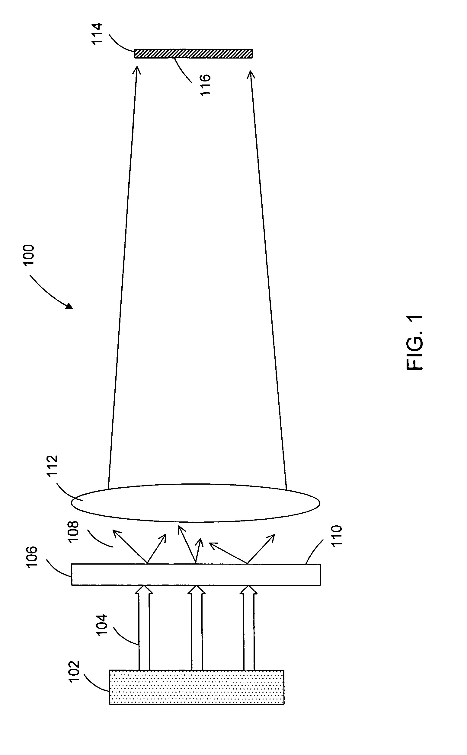
[0029]Referring to the drawings, FIG. 1 schematically illustrates an exemplary illumination system of the invention. Illumination system 100 comprise...


PUM


Abstract

A method and an optical system employing the same are provided for providing uniform illumination light with a desired illumination field using a surface diffuser.

Description

TECHNICAL FIELD OF THE INVENTION[0001]The present invention relates to the art of illumination systems, and more particularly to the art of illumination systems for use in display systems that employ spatial light modulators.BACKGROUND OF THE INVENTION[0002]During the past several years, solid state light sources, such as lasers and light-emitting-diodes (LEDs) have found recent application in display systems that employ spatial light modulators, such as liquid-crystal-displays and micromirror-based displays. This arises from the fact that solid state light sources when used in projection systems with spatial light modulators are superior over traditional arc lamps in many aspects, such as compact size, longer lifetime, and a narrower bandwidth.[0003]Using solid state light source in display systems, however, is also challenging. One of the challenges is a uniform image shape that matches the shape of the spatial light modulator surface. A solid state light source, such as a laser, ...

Claims


Application Information

Patent Timeline
IPC IPC(8): G03B21/00
CPCG03B21/00G03B21/005
Inventor BARTLETT, TERRY ALAN
Owner TEXAS INSTR INC
Why Eureka
Try Eureka