Directionally-adjustable LED spotlight

a technology of led spotlights and directional adjustment, which is applied in the direction of landing aids, lighting and heating apparatus, lighting support devices, etc., can solve the problems of disproportionately difficult to effectively position and lock the spotlight in place, and achieve the effect of convenient heat transfer, increased surface area, and sufficient heat transfer

Active Publication Date: 2008-04-03
IDEAL IND LIGHTING LLC
View PDF40 Cites 60 Cited by
  • Summary
  • Abstract
  • Description
  • Claims
  • Application Information

AI Technical Summary

Benefits of technology

[0013]In yet another preferred embodiment of the current invention, the heat sink and the ball portion of the LED-array-bearing structure are made from a heat-conducting material such as metal and the heat sink includes a plurality of fins extending outwardly from the ball-shaped LED-array-bearing structure. This construction from a heat conducting material facilitates the transfer of heat from the LEDs to the heat sink and the fins provide increased surface area from which the heat can dissipate.
[0014]This invention is based in part on the discovery

Problems solved by technology

Furthermore, this fixed relationship between the heat sink and the LED array has caused difficulty in designing an adjustable spotlight type fixture while utilizing LEDs, because the combination of the heat sink with the LED array, leads to an elongated arrangement that is difficult to

Method used


Image

  • Directionally-adjustable LED spotlight
  • Directionally-adjustable LED spotlight
  • Directionally-adjustable LED spotlight

Examples


Embodiment Construction

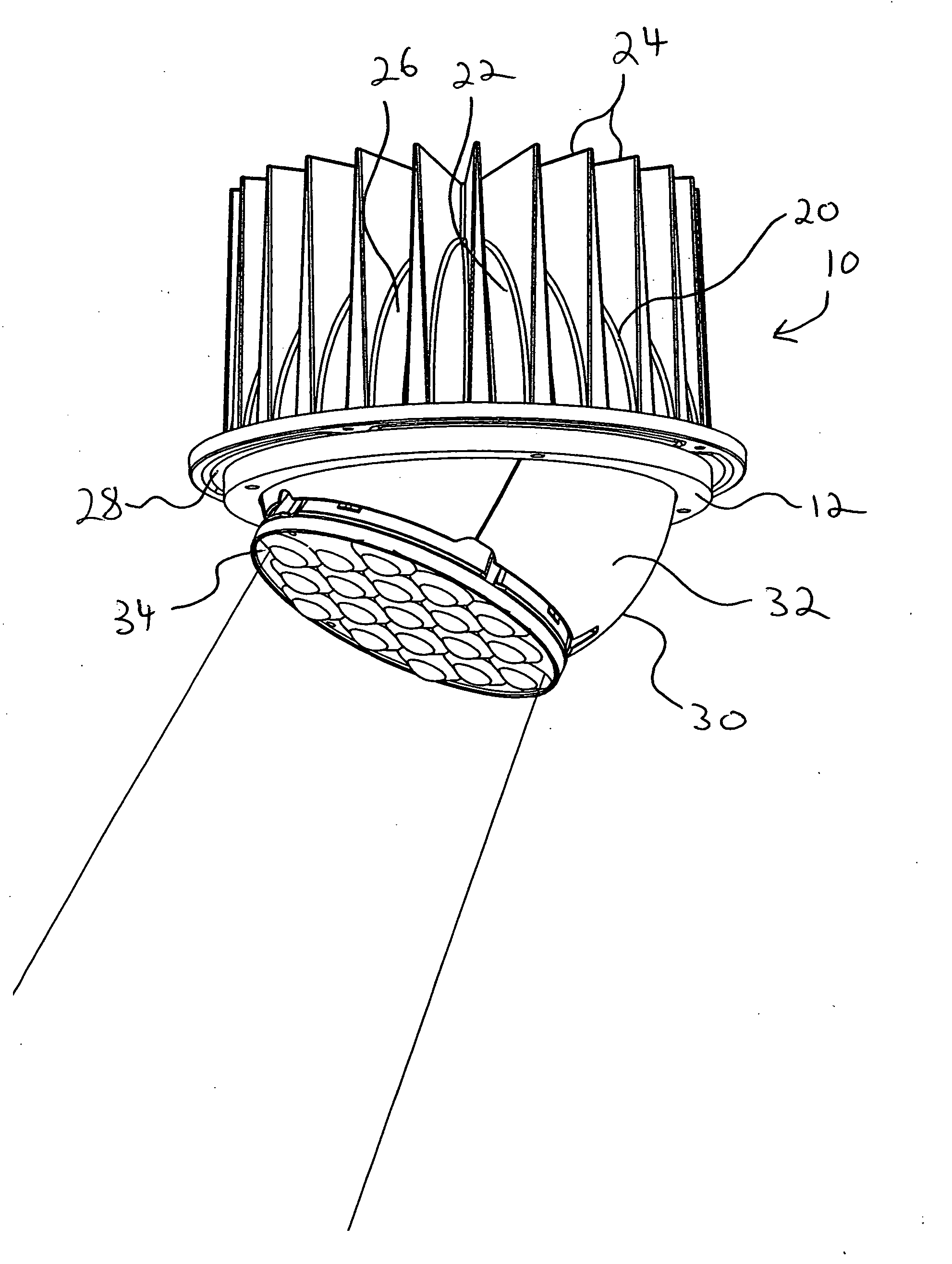
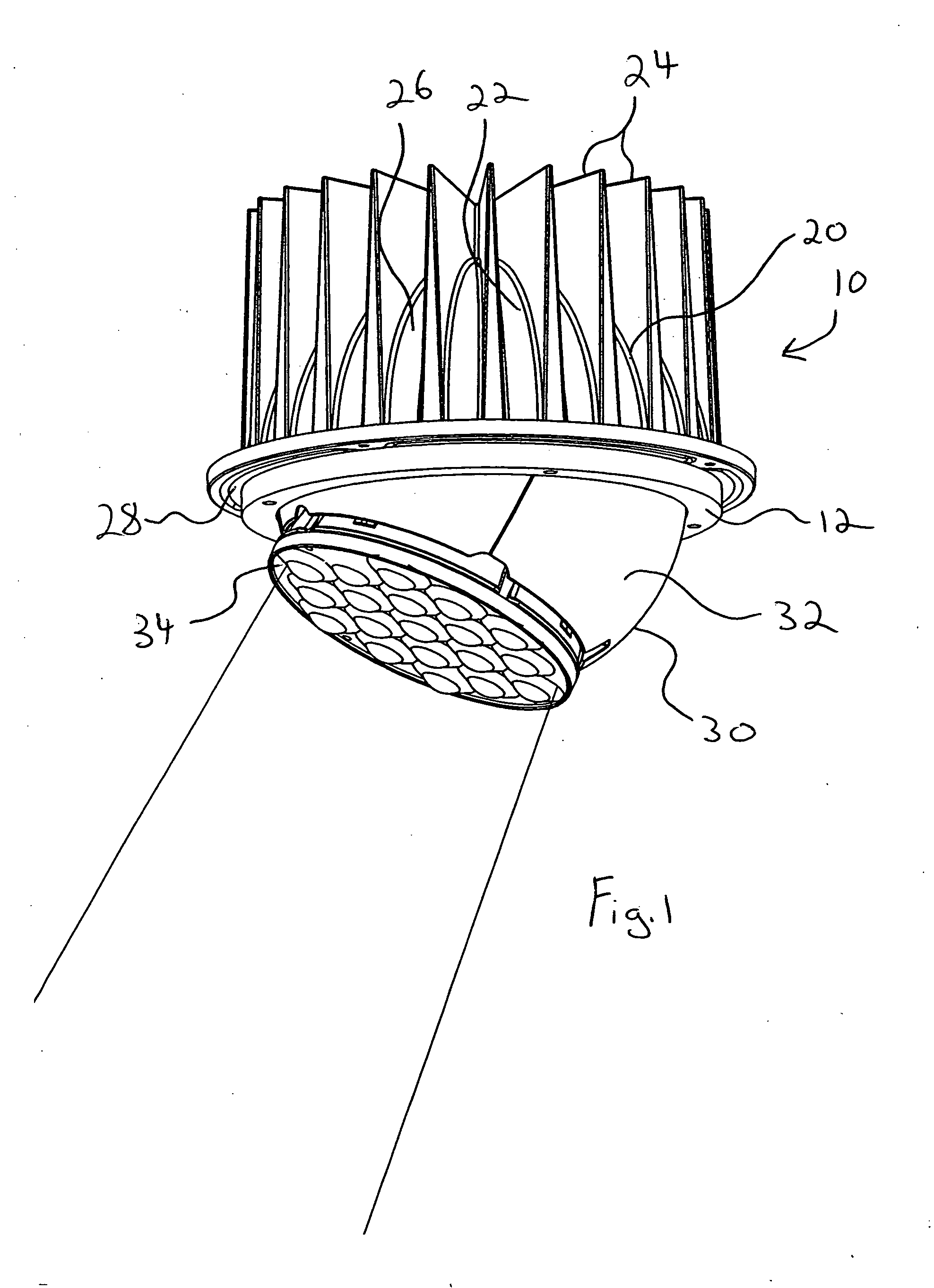
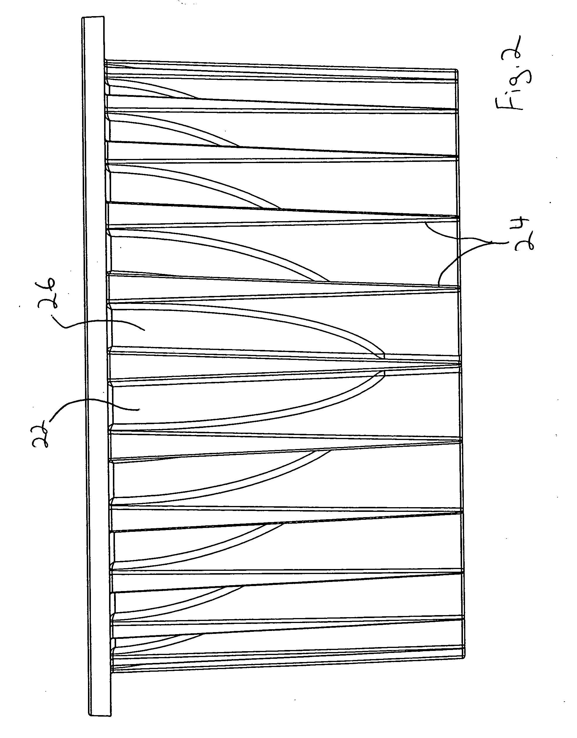
[0021]FIG. 1 illustrates a preferred embodiment of a directionally-adjustable LED spotlight 10 of the current invention. The LED spotlight 10 includes a fixed heat sink 20 and an LED-array-bearing structure 30. As seen in FIG. 2, the heat sink 20 is in a socket shape shown in the socket portion 22 and further includes a plurality of fins 24 that extend outwardly from an outer surface 26 of the heat sink 20.

[0022]Referring again to FIG. 1, the LED-array-bearing structure 30 includes a ball portion 32 and an LED array 34. As can be seen in FIGS. 3a and 3b, the ball portion 32 is sized to fit inside the socket portion 22 of the heat sink 20. Furthermore, the ball portion 32 is made of metal and is hollow. The ball and socket design of the heat sink 20 and the LED-array-bearing structure 30 allow for the entirety of the socket portion 22 of the heat sink 20 to be in contact with the ball portion 32 of the LED-array-bearing structure 30. This contact ensures a heat transfer relationship ...


PUM


Abstract

The inventive directionally-adjustable LED spotlight is comprised of a fixed heat sink and an LED-array-bearing structure. The LED-array-bearing structure is adjustably attached in a heat transfer relationship to the fixed heat sink.

Description

FIELD OF THE INVENTION[0001]This invention is related generally to light fixtures and, more particularly, to LED (Light Emitting Diodes) spotlights that include the capability of being directionally adjusted.BACKGROUND OF THE INVENTION[0002]In LED light fixtures, heat management is a highly important criteria since LEDs produce heat that is directed primarily in the direction opposite from the light emanation. Therefore, it is desirable to have a heat sink or other heat dissipation apparatus located behind the LED array. This need for a heat sink has led to the configuration of LED fixtures to include a heat sink in a fixed relationship to the LED array.[0003]Furthermore, this fixed relationship between the heat sink and the LED array has caused difficulty in designing an adjustable spotlight type fixture while utilizing LEDs, because the combination of the heat sink with the LED array, leads to an elongated arrangement that is difficult to reposition and leads to tall fixtures when...

Claims


Application Information

Patent Timeline
IPC IPC(8): F21V29/00
CPCF21V14/02F21V21/30F21V29/77F21Y2101/02F21V29/004F21Y2115/10F21V29/763F21V29/89
Inventor WALCZAK, STEVEN R.WILCOX, KURTGUILLIEN, WAYNE
Owner IDEAL IND LIGHTING LLC
Why Eureka
Try Eureka