Packet loss rate calculation system

a packet loss and calculation system technology, applied in data switching networks, frequency-division multiplexes, instruments, etc., can solve the problems of inability to calculate packet loss rate in forward and return paths individually, and inability to calculate packet loss rate with high accuracy

Inactive Publication Date: 2008-04-03
FUJITSU LTD
View PDF2 Cites 41 Cited by
  • Summary
  • Abstract
  • Description
  • Claims
  • Application Information

AI Technical Summary

Benefits of technology

[0010] It is an object of the present invention to at least partially solve the problems in the conventional technology.

Problems solved by technology

These conventional methods have problems that it is unable to calculate packet loss rate with high accuracy or it is unable to calculate packet loss rate in forward and return path individually.
Namely, according to the technology disclosed in Japanese Patent Application Laid-open No. 2005-269170, there is a problem that it is unable to calculate packet loss rate with high accuracy because the packet loss rate is calculated by using time information and therefore there is not necessarily cause-and-effect relationship between the time information and the packet loss rate.
Furthermore, according to the conventional technology described above, there is another problem that it is unable to calculate the packet loss rate in a forward path from the sending probe to the receiving probe or a backward path from the receiving probe to the sending probe, because the packet loss rate is calculated only through a round trip path between the sending probe and the receiving probe.

Method used


Image

  • Packet loss rate calculation system
  • Packet loss rate calculation system
  • Packet loss rate calculation system

Examples


first embodiment

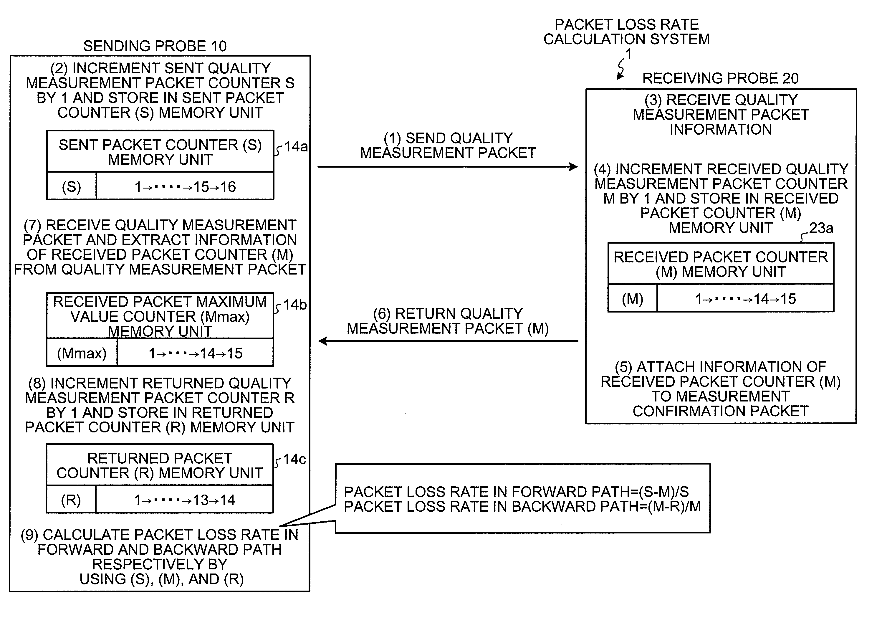
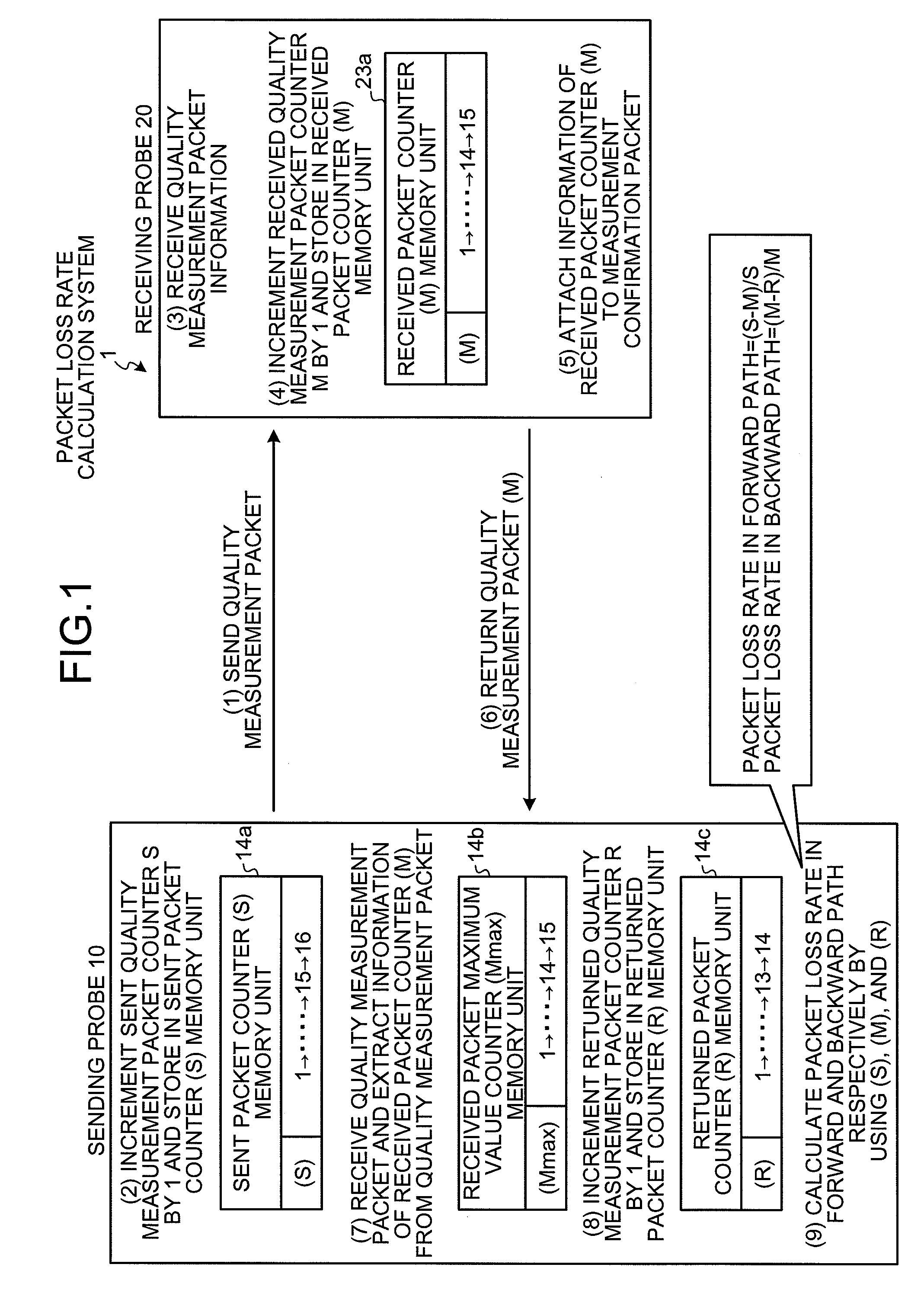
[0046]FIG. 1 is a diagram for explaining an outline and features of a packet loss rate calculation system 1 according to the present invention.

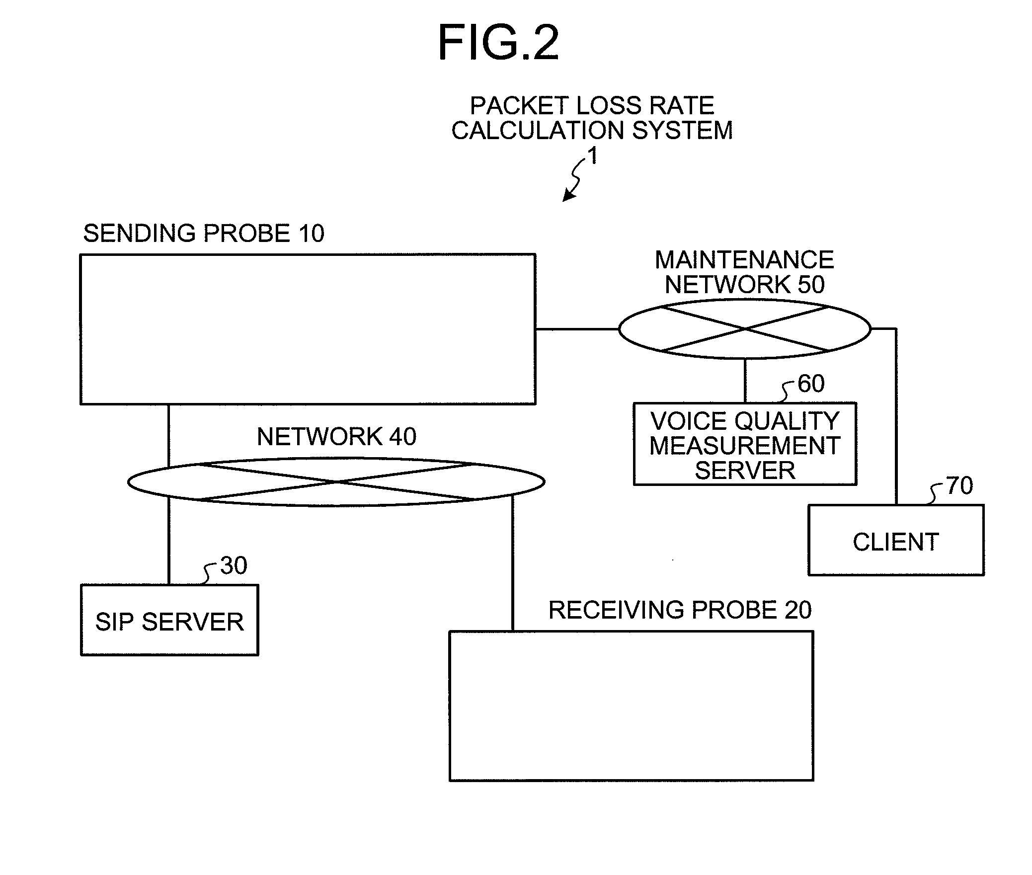
[0047] In the packet loss rate calculation system 1 according to the first embodiment, quality measurement packets for quality measurement are sent and received between a sending probe 10 and a receiving probe 20 which are located at arbitrary measuring points, and a packet loss rate between the measuring points is calculated by using information obtained from the quality measurement packets. The packet loss rate calculation system 1 features in calculation of packet loss rate with high accuracy in a forward path as well as in a backward path.

[0048] Explaining the main feature specifically, the sending probe 10 includes, as shown in FIG. 1, a sent packet counter memory unit 14a to store a packet count of quality measurement packets sent to the receiving probe 20, a received packet maximum value counter memory unit 14b to store the maximum va...

second embodiment

[0106] In the packet loss rate calculation system 1a a measurement confirmation packet is sent and received between a sending probe 10a and a receiving probe 20a, and packet loss rate between the measuring points is calculated by using the information obtained from the measurement confirmation. The packet loss rate calculation system 1a features in that, even when the last quality measurement packet sent from the sending probe to the receiving probe was lost, the packet loss rate can be calculated by sending the received packet count stored in the receiving probe again at the end of quality measurement.

[0107] Describing the main feature specifically, as shown in FIG. 17, the sending probe 10a of the packet loss rate calculation system 1a further sends a measurement confirmation packet to the receiving probe 20a after all quality measurement packets have been sent to the receiving probe 20a (see FIG. 17 (1)).

[0108] The receiving probe 20a receives the measurement confirmation packe...

third embodiment

[0136] In the packet loss rate calculation system 1b a measurement confirmation packet is exchanged between a sending probe 10b and a receiving probe 20b during send of quality measurement packets, and by using the information obtained from the measurement confirmation packet, packet loss rate between the measuring points at that time point is calculated. The packet loss rate calculation system 1b is mainly characterized in that, even when a quality measurement packet was lost during measurement of packet loss rate, the packet loss rate at that time point can be calculated.

[0137] Describing the feature in particular, the sending probe 10b in the packet loss rate calculation system 1b attaches a sent packet counter (S) stored in the sent packet counter memory unit 14a to a measurement confirmation packet (see FIG. 25 (1)) at arbitrary timing during send of quality measurement packets, and send the measurement confirmation packet to the receiving probe 20b (see FIG. 25 (2)).

[0138] T...


PUM


Abstract

A sending probe sends a quality measurement packet to a receiving probe, and increments a sent packet counter every time the quality measurement packet is sent. A receiving probe receives the quality measurement packet from the sending probe, and attaches a received packet counter to the quality measurement packet and returns the quality measurement packet to the sending probe. The sending probe receives a returned quality measurement packet, extracts a received packet count from the quality measurement packet, and calculates a packet loss rate by using a difference between the sent packet counter and the received packet counter and a difference between the received packet counter and the returned packed counter.

Description

BACKGROUND OF THE INVENTION [0001] 1. Field of the Invention [0002] The present invention relates to a technology for calculating a packet loss rate between measuring points based on information obtained from packets for quality measurement. [0003] 2. Description of the Related Art [0004] There is a conventional method of active measurement of service quality in which packets for quality measurement are actively sent to simulate arbitrary service for the purpose of measurement of a service quality (for example, a packet loss rate). To implement such a measurement of service quality, a sending probe and a receiving probe as measuring device (such as probe or server) for arbitrary quality measurement are located at arbitrary measuring points in the network. The sending probe generates and sends actively packets for quality measurement between the sending probe and the receiving probe, one or multiple receiving probes receive these packets and returned them to the sending probe, and qu...

Claims


Application Information

Patent Timeline
Patent Type & Authority Applications(United States)
IPC IPC(8): H04L12/56H04L12/70
CPCH04L43/12H04L43/0829
Inventor EBUCHI, RYUICHIETOH, FUMIHARU
Owner FUJITSU LTD
Why Eureka
Try Eureka