Anchor bar and arrangement for reinforcing existing components against punching shears with such anchor bar

a technology of anchor bars and existing components, which is applied in the direction of dowels, structural elements, building components, etc., can solve the problems of inability to economically produce mass production parts, increase the manufacturing cost of anchor bars, and the non-embedded region of anchor bars is not precisely guided in the borehole, so as to prevent the soiling of the working region

Inactive Publication Date: 2008-04-03
HILTI AG
View PDF25 Cites 14 Cited by
  • Summary
  • Abstract
  • Description
  • Claims
  • Application Information

AI Technical Summary

Benefits of technology

[0021] Advantageously, the anchor bar is provided with at least one centering element. The centering element is formed, e.g., as an elastic annular section the radially outer extension of which is greater than the inner diameter of a conventionally used borehole, and the inner diameter of which is slightly smaller than the outer diameter of the anchor bar. The at least one centering element ensures a complete, uniform arrangement of the anchor bar in the borehole filled with a hardenable material. Preferably, the at least one centering element has through-openings for the hardenable mass and through which the displaced mass rises toward the borehole mouth when the anchor bar is...

Problems solved by technology

The drawback of the anchor bar of the U.S. Pat. No. 4,662,795 consists in that the anchor bar is not completely embedded in the hardenable mass and, therefore, the non-embedded region of the anchor bar is not precisely guided in the borehole.
The large material consumption increases manufacturing costs of such anchor bar, and it cannot be economically produced as a mass production part.
If the slab floors are underdimensioned with respect to their reinforcement or they become overloaded, e.g., as a result of increase of a load applied thereto, the constructional parts fail, primarily, as a result of flection or caving in.
Against that, the failure of a constructional component at a punchi...

Method used


Image

  • Anchor bar and arrangement for reinforcing existing components against punching shears with such anchor bar
  • Anchor bar and arrangement for reinforcing existing components against punching shears with such anchor bar
  • Anchor bar and arrangement for reinforcing existing components against punching shears with such anchor bar

Examples


first embodiment

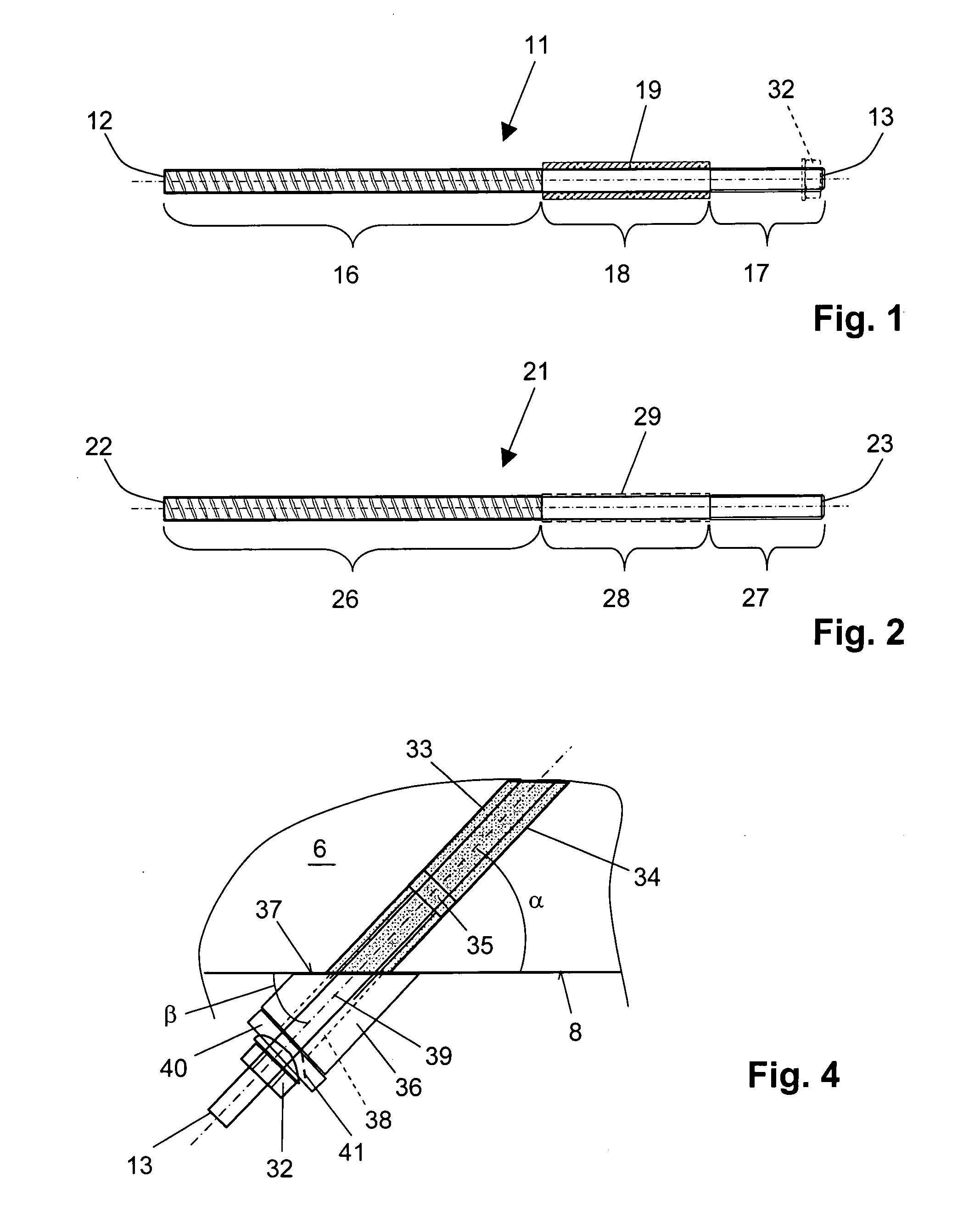
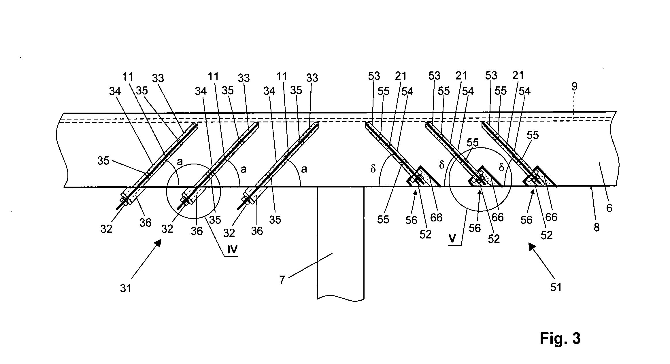
[0038] With the arrangement 31 as shown with reference to FIG. 3, to the left of the pillar 7, and in detail in FIG. 4, first, boreholes 34 are formed up to the level of an upper reinforcement 9 of the slab floor 6 and at an angle α of about 45° to the outer surface 8 of the slab floor 6 and toward the pillar 7. Then, each borehole 34 is filled with mortar form a hardenable mass 33. Advantageously, a hold-up plug is used that prevents to a large extent undesirable air pockets in the hardenable mass 33 during the filling process. The anchor bar 11 is inserted in the borehole 34 filled with the hardenable mass 33. A bevel washer 36 is placed over the free end 13 of the anchor bar 11. The angle β of the bevel 37 of the washer 36 to the axis 39 of the through-opening 38 for the anchor bar 11 corresponds to the angle α of the borehole 34 to the surface 8 of the slab floor. There is further provided a sealing washer 40 that is secured with the preloading means 32 and that is provided wit...

second embodiment

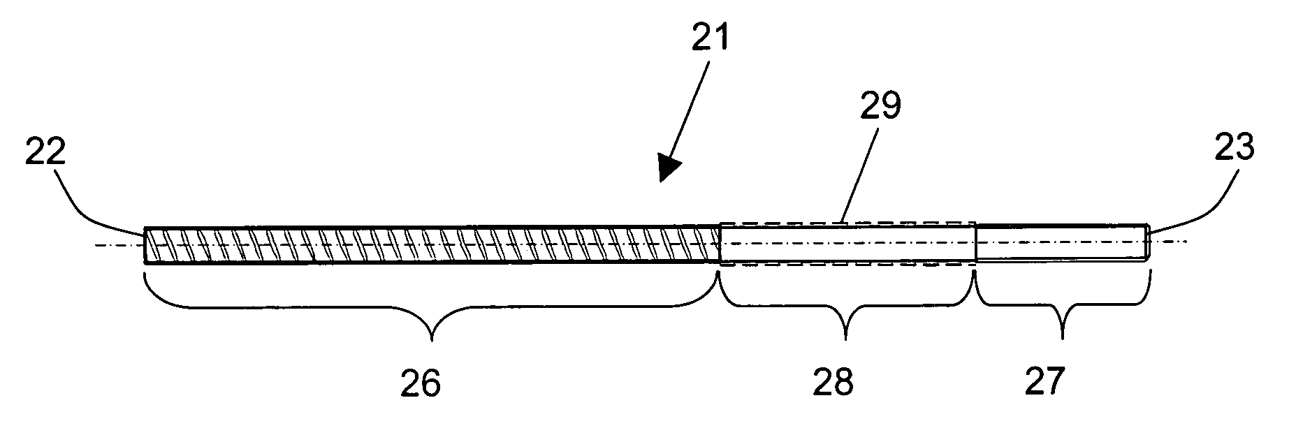
[0039] With the arrangement 51 as shown with reference to FIG. 3, to the right of the pillar 7, and in detail in FIGS. 5-6, first, boreholes 54 are formed up to the level of an upper reinforcement 9 of the slab floor 6 and at an angle β of about 50° to the outer surface 8 of the slab floor 6 and toward the pillar 7. Then, at each borehole 54 and centrally thereto, a recess 56, which opens toward the outer surface 8 of the slab floor 6, is formed, e.g., with an annular core bit. Then, each borehole 54 is filled with a mortar from hardenable mass 53, and a pot-shaped reinforcing element 66 is placed in the recess 56. Then or, alternatively, before placement of the reinforcing element 66 in the recess 56, the anchor bar is inserted in the borehole 54. Over the free end 23 of the anchor bar 21, a two-part washer 61, which serves as a support element, is mounted and is secured with the preloading means 52. The washer 61 has a first part 62 with a convex receptacle and a second part 63 w...


PUM


Abstract

An anchor bar includes an anchoring section (16; 26), a threaded section (17; 27), and an intermediate section (18; 28) located between the anchoring section (16; 26) and the threaded section (17; 27) and having an anti-adhesive surface.

Description

BACKGROUND OF THE INVENTION [0001] 1. Field of the Invention [0002] The present invention relates to an anchor bar having an anchoring section and a threaded section. The present invention further relates to an arrangement for reinforcing existing constructional components against punching shears with the anchor bar. [0003] 2. Description of the Prior Art [0004] Anchor bars are formed as bar-shaped anchor rods which, e.g., are driven in boreholes filled with a hardenable mass such as, e.g., a mortar, and are preloaded with a preloading element after the start of the bonding process. E.g., U.S. Pat. No. 4,662,795 discloses a rock anchor that can serve an anchor bar. The anchor bar of the U.S. Pat. No. 4,662,795 has anchoring section in the form of a profiled section that extends from a first end, and a threaded section that extends from the second end of the anchor bar and adjoins the anchoring profiled section. The borehole is partially filled with a hardenable mass, and the anchor ...

Claims


Application Information

Patent Timeline
IPC IPC(8): F16B13/06
CPCE01D22/00E04G23/0218E04C5/0645
Inventor BEE, PETERDE SMET, CAMIELKUNZ, JAKOBMUENGER, FRITZRANDL, NORBERT
Owner HILTI AG
Why Eureka
Try Eureka