Blood pressure monitor

Inactive Publication Date: 2008-04-03
TRIAGE WIRELESS
View PDF61 Cites 124 Cited by
  • Summary
  • Abstract
  • Description
  • Claims
  • Application Information

AI Technical Summary

Benefits of technology

[0012]To address any deficiencies in the prior art, the present invention provides blood pressure monitor featuring a substrate that includes small-scale optical, electrical, and acoustic sensors. The substrate, for example, may be a single, continuous component, or alternatively may consist of a first component (e.g. a disposable adhesive material) that connects or attaches

Problems solved by technology

Typically a high blood pressure results in a shorter PTT.
PTT-based measurements of blood pressure are complicated by a number of factors, one of which is the many time-dependent processes asso

Method used


Image

  • Blood pressure monitor
  • Blood pressure monitor
  • Blood pressure monitor

Examples


Embodiment Construction

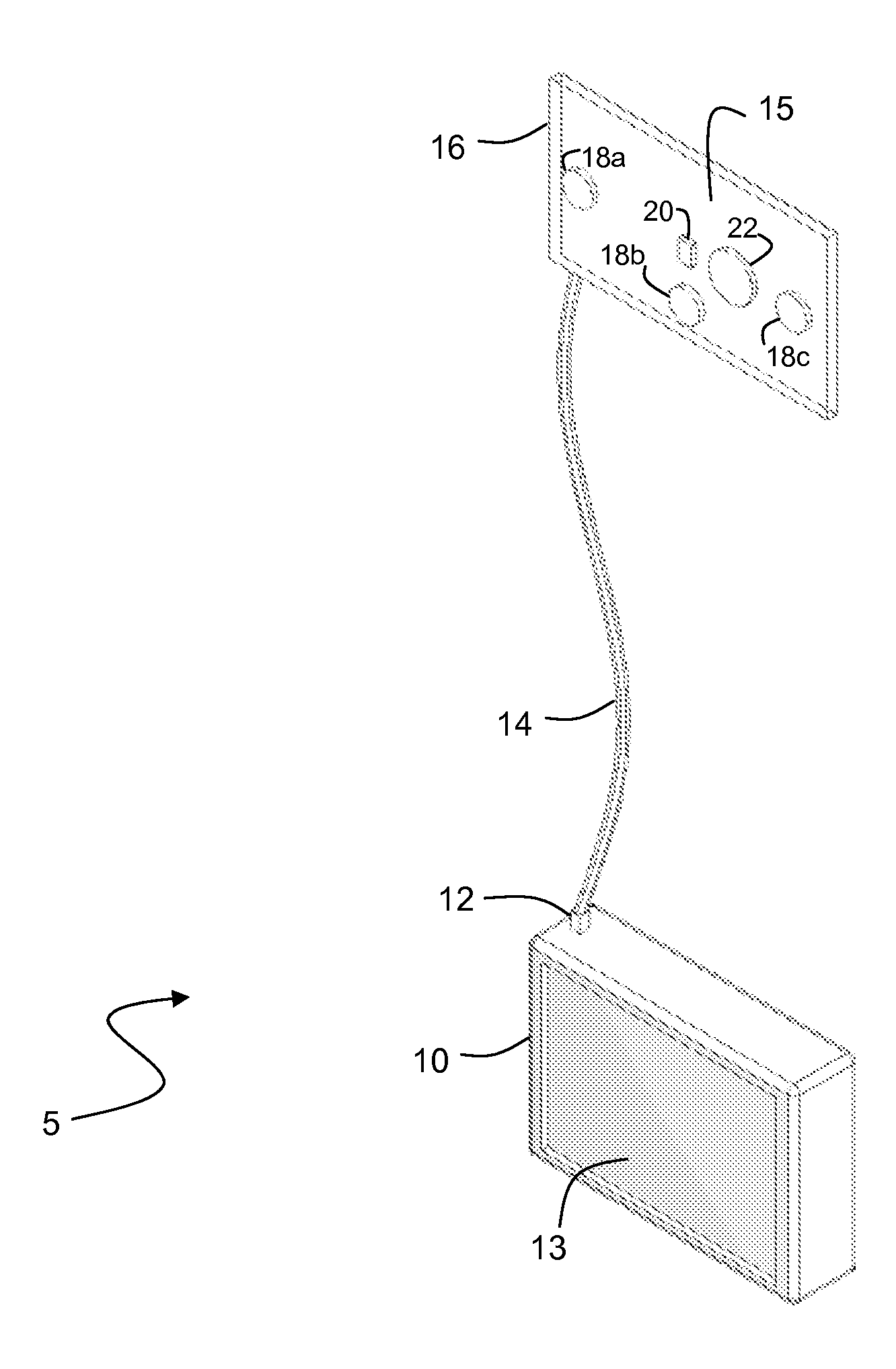
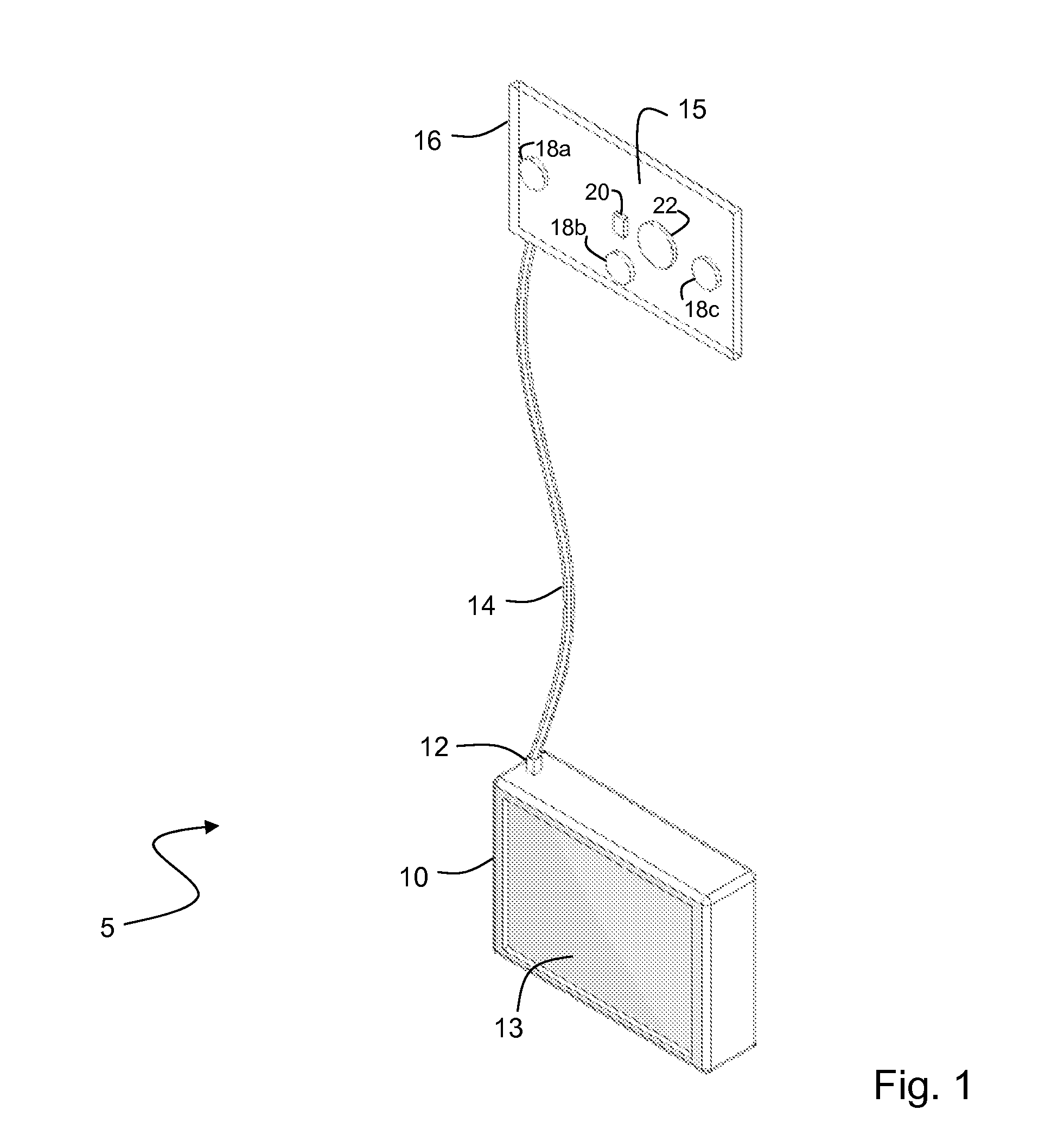
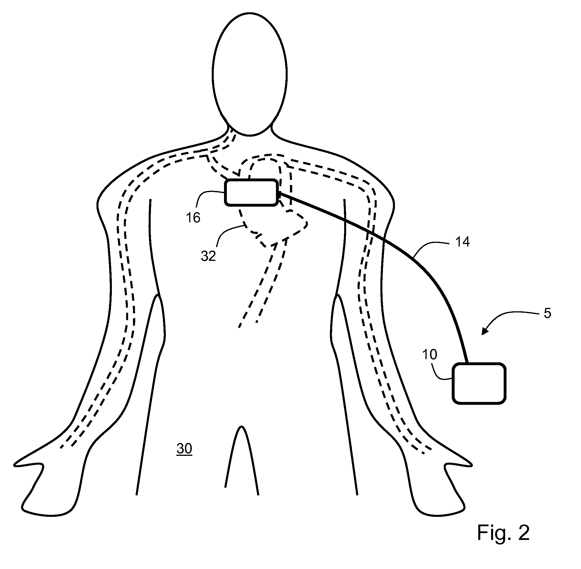
[0036]FIG. 1 shows a preferred embodiment of a blood pressure monitor 5 according to the invention that includes a console 10 that attaches to a flexible foam pad 16 through a cable 14. The flexible foam pad 16 includes a substrate 15 that supports sensors that measure time-dependent electrical, optical, and acoustic waveforms (shown in FIGS. 3A, 3B). The substrate 15 is preferably a flexible printed circuit board that adheres to the foam pad 16. During operation, the flexible foam pad 16 preferably contacts an area below a patient's sternal notch to measure the various waveforms from a patient. A microprocessor in the console 10 analyzes the waveforms to determine the systolic time intervals, which are then processed with an algorithm and a weighted average to determine the patient's real-time blood pressure.

[0037]The flexible foam pad 16 preferably includes three electrodes 18a-c that measure two electrical signals and a ground (or other) signal from the patient. Two of the electr...


PUM


Abstract

The invention provides a method for measuring a blood pressure value of a user featuring the following steps: 1) generating optical, electrical, and acoustic waveforms with, respectively, optical, electrical, and acoustic sensors attached to a single substrate that contacts a user; 2) determining at least one parameter by analyzing the optical and acoustic waveforms; and 3) processing the parameter to determine the blood pressure value for the user.

Description

CROSS REFERENCES TO RELATED APPLICATION[0001]Not ApplicableSTATEMENT REGARDING FEDERALLY SPONSORED RESEARCH OR DEVELOPMENT[0002]Not ApplicableBACKGROUND OF THE INVENTION[0003]1. Field of the Invention[0004]The present invention relates to medical devices for monitoring vital signs such as blood pressure.[0005]2. Description of the Related Art[0006]Pulse transit time (‘PTT’), defined as the transit time for a pressure pulse launched by a heartbeat in a patient's arterial system, has been shown in a number of studies to correlate to both systolic and diastolic blood pressure. In these studies PTT is typically measured with a conventional vital signs monitor that includes separate modules to determine both an electrocardiogram (ECG) and pulse oximetry. During a conventional PTT measurement, multiple electrodes typically attach to a patient's chest to determine a time-dependent ECG characterized by a sharp spike called the ‘QRS complex’. This feature indicates an initial depolarization ...

Claims


Application Information

Patent Timeline
IPC IPC(8): A61B5/02
CPCA61B5/0059A61B5/02028A61B5/021A61B5/7239A61B5/0402A61B5/6833A61B7/04A61B5/026A61B5/02125A61B5/318
Inventor BANET, MATTHEW JOHNTHOMPSON, MICHAEL JAMESZHOU, ZHOU
Owner TRIAGE WIRELESS
Why Eureka
Try Eureka