Wire holder

a wire holder and wire technology, applied in the direction of insulated conductors, cable connections, coupling devices, etc., can solve the problems of contact failure between the terminal on the end of the wire and the mating terminal, the binding band is not secured firmly to the wire fixing portion, and the binding band will slip on the wire fixing portion

Active Publication Date: 2008-04-10
SUMITOMO WIRING SYST LTD
View PDF5 Cites 6 Cited by
  • Summary
  • Abstract
  • Description
  • Claims
  • Application Information

AI Technical Summary

Benefits of technology

[0009]The wire fixing portion preferably is formed with at least one slit and the tightening diameter at the wire fixing portion decreases as the slit is narrowed. The decrease of the tightening diameter at the slit restricts displacements of the fixing band on the wire fixing portion and suppresses displacements of the wires relative to the wire fixing portion.
[0011]At least one surface of the wire fixing portion not facing the wires preferably is curved concavely. Thus, the fixing band easily can be fastened close to the wire fixing portion. Therefore the wires can be tightened firmly even if dimensional tolerances of the wire fixing portion and the fixing band are large.

Problems solved by technology

However, the binding band is not secured firmly to the wire fixing portion.
Thus, the binding band will slip on the wire fixing portion if the wires are subject to vibration and the wires can displace.
Displacement of the wires can cause contact failures between terminals on the ends of the wires and mating terminals, fine sliding abrasion, and the like.

Method used


Image

  • Wire holder
  • Wire holder
  • Wire holder

Examples


first embodiment

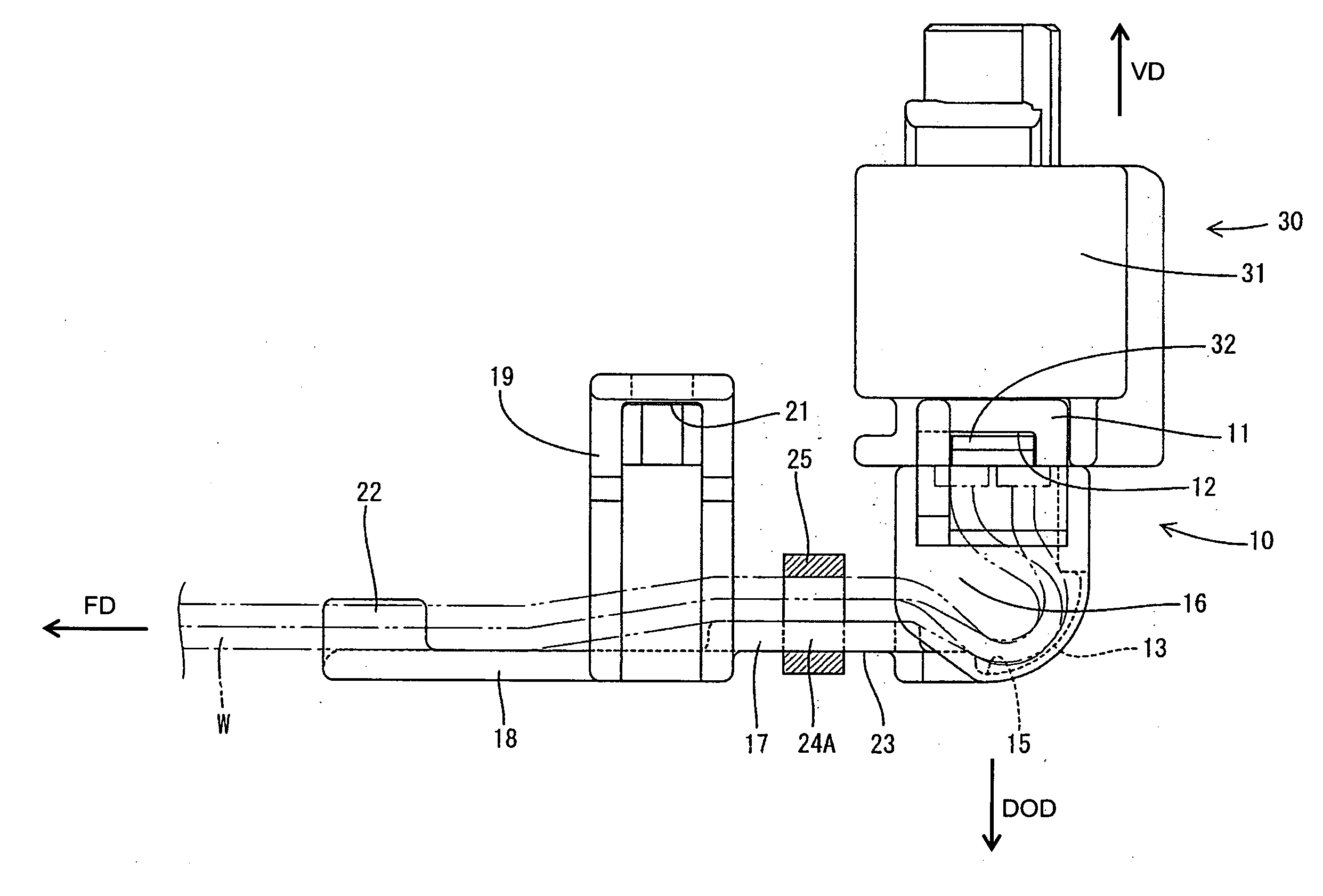
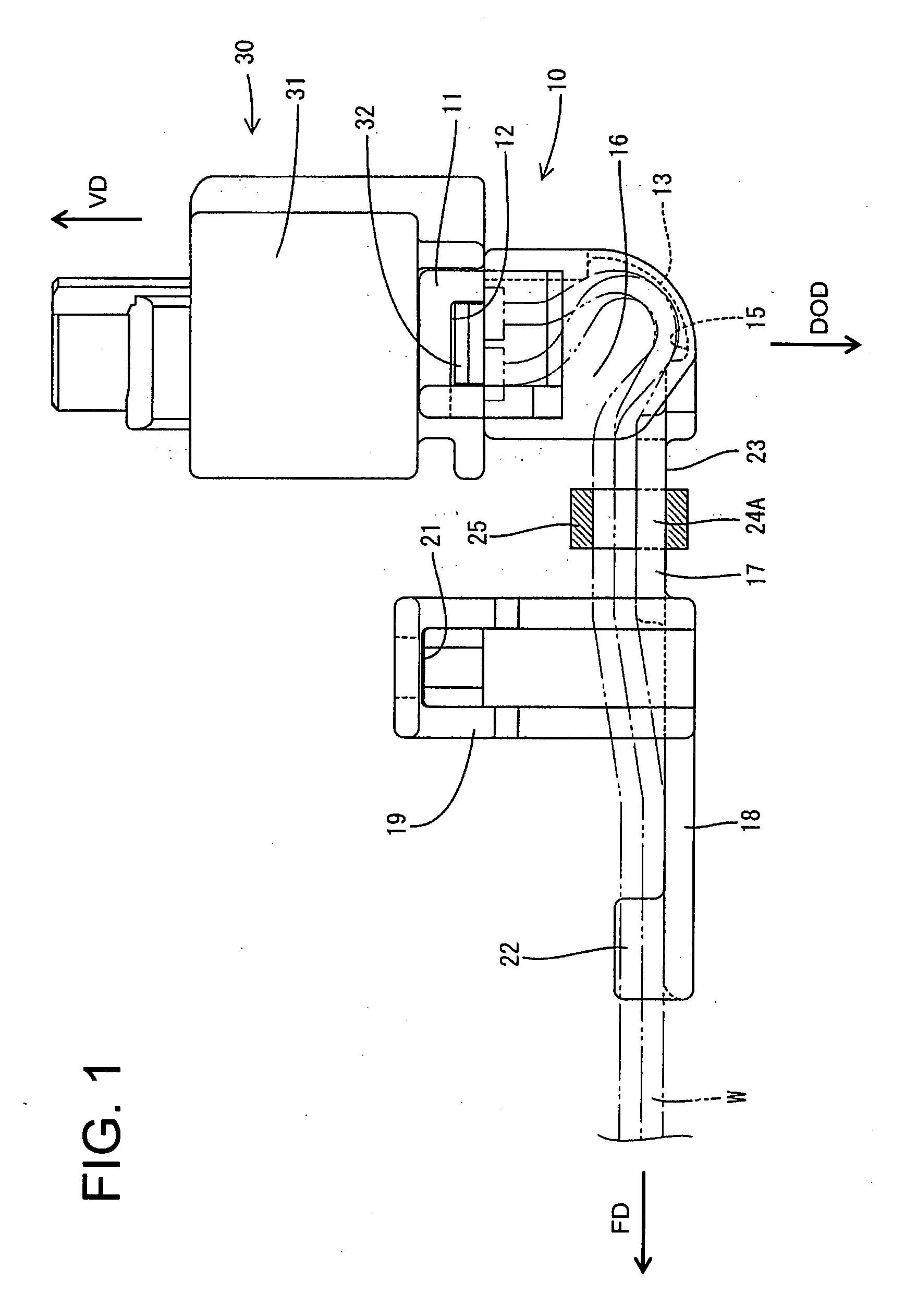
[0029]A wire holder according to the invention is identified by the numeral 10 in FIGS. 1 to 8. The wire holder 10 is mountable to a connector 30 connectable with a device-side connector (not shown) for leading wires W drawn out from the connector 30 and fixing them to a vehicle body.

[0030]To provide a frame of reference, the vertical orientation of FIG. 1 is referred to herein as the vertical direction VD and is parallel to a draw-out direction DOD of the wires W. A direction in which the wires W are bent is referred to as the forward direction FD is substantially normal to the vertical direction VD and the draw-out direction DOD of the wires W.

[0031]The connector 30 includes a housing 31 substantially in the form of a rectangular parallelepiped made e.g. of a synthetic resin and terminal fittings (not shown) are accommodated therein. The terminal fittings are inserted substantially vertically into the housing 31 and are arrayed in front and back rows. The wires W connected with th...

second embodiment

[0075]The rear surface 54 and opposite side surfaces 53 of the wire fixing portion 51 are recessed in the However, only the rear surface or only one of the side surfaces may be recessed.

[0076]Although the rear surface 54 and the opposite side surfaces 53 of the wire fixing portion 51 are concave curves in the second embodiment, the invention is not limited thereto and any shapes may be adopted provided that the tightening diameter of the fixing band is smallest at the intermediate part of the wire fixing portion.

[0077]Although the invention is applied to the wire holder 10 (50) for leading and holding the wires W drawn out from the housing in the specified direction in the above embodiments, the invention is not limited thereto and may be applied to a wire cover for protecting ends of wires drawn out from a housing by surrounding the wires.

[0078]The wire fixing portion 17 (51) is located in the resilient restoring direction of the bent wires W in the foregoing embodiments, but it m...


PUM


Abstract

A wire fixing portion (17) is so formed with a slit (24) as to minimize a tightening diameter at the wire fixing portion (17) by narrowing the slit (24). Thus, there is no likelihood of displacing a fixing band (25) fastened to a middle part of the wire fixing portion (17) toward a side where the tightening diameter is larger. Accordingly, displacements of the fixing band (25) relative to the wire fixing portion (17) are restricted, wherefore displacements of the wires (W) relative to the wire fixing portion (17) are suppressed.

Description

BACKGROUND OF THE INVENTION[0001]1. Field of the Invention[0002]The invention relates to a wire holder for leading and holding wires drawn out from a housing in a specified direction.[0003]2. Description of the Related Art[0004]U.S. Pat. No. 6,762,363 discloses a wire holder that is mounted to a housing for holding wires drawn out from the housing and leading the wires in a specified direction. The wire cover has a wire lead-out opening with an open rear end. The wires drawn out from the housing are bent in the wire cover and led out backward through the wire lead-out opening.[0005]A wire fixing portion projects back at the wire lead-out opening and a binding band is wound with the wires placed along the wire fixing portion. The wires then are pressed to the wire fixing portion by tightening the binding band.[0006]The tightly fastened binding band bites in insulation coatings of the wires and fixes firmly to the wires. However, the binding band is not secured firmly to the wire fixi...

Claims


Application Information

Patent Timeline
Patent Type & Authority Applications(United States)
IPC IPC(8): F16L3/22
CPCH01R13/5804
Inventor KOBAYASHI, TOMOHIKOHATA, TAKAO
Owner SUMITOMO WIRING SYST LTD
Why Eureka
Try Eureka