Printhead IC with multi-stage print data loading and firing

a printhead and data technology, applied in the field of inkjet printers, can solve the problems of increasing the power increasing the size of the drive fet, and reducing the density of the nozzle of the printhead

Active Publication Date: 2008-04-10
SILVERBROOK RES PTY LTD +1
View PDF6 Cites 19 Cited by
  • Summary
  • Abstract
  • Description
  • Claims
  • Application Information

AI Technical Summary

Problems solved by technology

This allows much higher print speeds but is more complicated in terms of controlling the operation of a much larger array of nozzles.
However, increasing the power of the drive FET increases its size.
This enlarges the wafer area occupied by the nozzle and its associated circuitry and therefore reduces the nozzle density of the printhead.
Reducing the nozzle density is detrimental to print quality and compact printhead design.

Method used


Image

  • Printhead IC with multi-stage print data loading and firing
  • Printhead IC with multi-stage print data loading and firing
  • Printhead IC with multi-stage print data loading and firing

Examples


Embodiment Construction

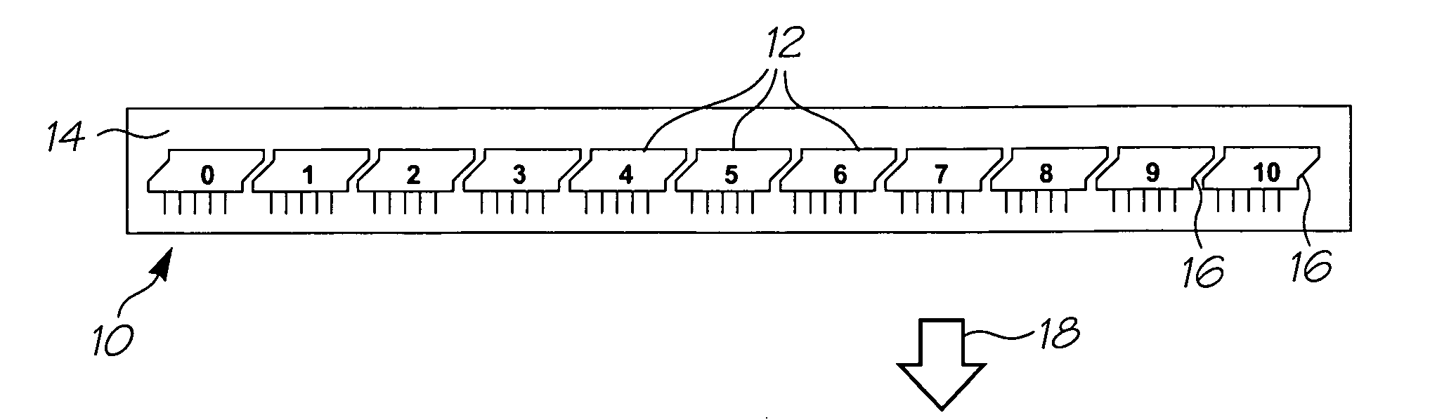
[0188]The Applicant has developed a range of printhead devices that use a series of printhead integrated circuits (ICs) that link together to form a pagewidth printhead. In this way, the printhead IC's can be assembled into printheads used in applications ranging from wide format printing to cameras and cellphones with inbuilt printers. One of the more recent printhead IC's developed by the Applicant is referred to internally as wide range of printing applications. The Applicant refers to these printhead IC's as ‘Udon’ and the various aspects of the invention will be described with particular reference to these printhead IC's. However, it will be appreciated that this is purely for the purposes of illustration and in no way limiting to the scope and application of the invention.

Overview

[0189]The Udon printhead IC is designed to work with other Udon ICs to make a linking printhead. The Applicant has developed a range of linking printheads in which a series of the printhead IC's are m...


PUM


Abstract

A printhead IC comprising: an array of nozzles; drive circuitry for receiving print data and fire commands from a print engine controller; wherein during use, the drive circuitry receives the print data for the array in a plurality of sequential portions with a fire command at the end of each portion.

Description

FIELD OF THE INVENTION[0001]The present invention relates to the field of inkjet printers. In particular, the invention relates to inkjet printers that have printheads with a number of separate printhead integrated circuits (IC's) defining the nozzles that eject the ink or other printing fluid.CO-PENDING APPLICATIONS[0002]The following applications have been filed by the Applicant simultaneously with the present application:PUA001USPUA003USPUA004USPUA005USPUA006USPUA007USPUA008USPUA009USPUA010USPUA011USPUA012USPUA013USPUA014USPUA015USMTE001USMTE002USThe disclosures of these co-pending applications are incorporated herein by reference. The above applications have been identified by their filing docket number, which will be substituted with the corresponding application number, once assigned.CROSS REFERENCES TO RELATED APPLICATIONS[0003]Various methods, systems and apparatus relating to the present invention are disclosed in the following US Patents / Patent Applications filed by the ap...

Claims


Application Information

Patent Timeline
Patent Type & Authority Applications(United States)
IPC IPC(8): B41J29/38
CPCB41J2/0451B41J2/04515B41J2/04541B41J2/04545B41J2/04551B41J2/04563B41J2202/20B41J2/0458B41J2/04591B41J2/04596B41J2/1404B41J2002/14403B41J2/0457
Inventor SHEAHAN, JOHN ROBERTPULVER, MARK JACKSONMORAHAN, BRIAN CHRISTOPHERMOINI, ALIREZAGILLESPIE, TIMOTHY PETERWEBB, MICHAEL JOHNGANNON, MARCELLE LOUISASILVERBROOK, KIA
Owner SILVERBROOK RES PTY LTD
Why Eureka
Try Eureka