

Exposure Apparatus,Exposure Method, And For Producing Device
a technology an apparatus, applied in the field of a production device, can solve the problems of insufficient focus margin, difficulty in matching the substrate surface with the image plane of the projection optical system,
- Summary
- Abstract
- Description
- Claims
- Application Information
AI Technical Summary
Benefits of technology
Problems solved by technology
Method used
Image

Examples
first embodiment
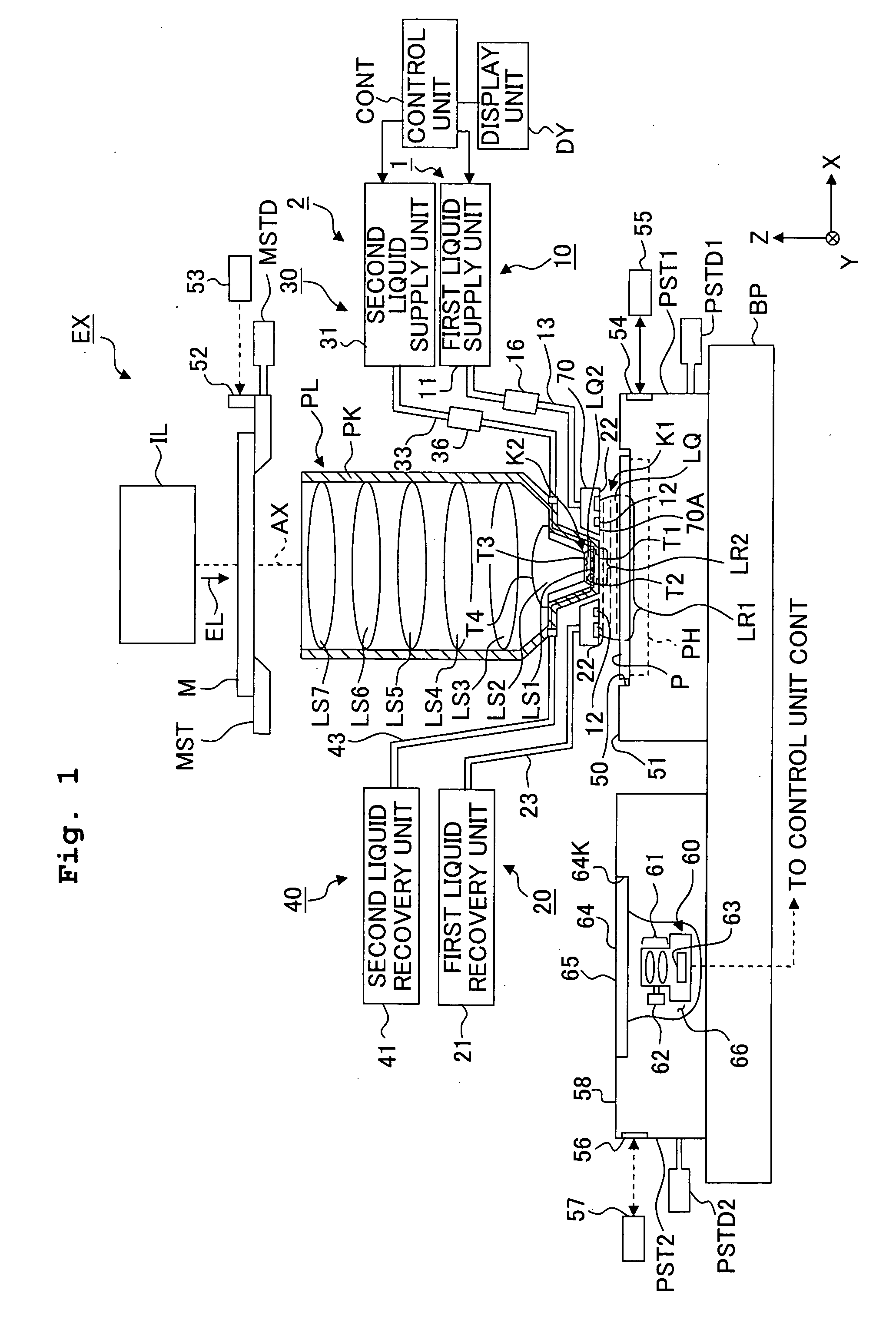
[0038]FIG. 1 is a schematic arrangement view illustrating an exposure apparatus EX according to a first embodiment. In FIG. 1, the exposure apparatus EX includes a mask stage MST which is movable while supporting a mask M, a substrate stage PST1 which includes a substrate holder PH for holding a substrate P and is movable while holding the substrate P on the substrate holder PH, a measuring stage PST2 which holds a measuring instrument for performing measurements relating to an exposure process and is movable independently from the substrate stage PST1, an illumination optical system IL which illuminates the mask M supported on the mask stage MST with exposure light beam EL, a projection optical system PL which projects an image of a pattern of the mask M illuminated with the exposure light beam EL onto the substrate P supported on the substrate stage PST1, and a control unit CONT which collectively controls the overall operation of the exposure apparatus EX. To the control unit CON...
second embodiment
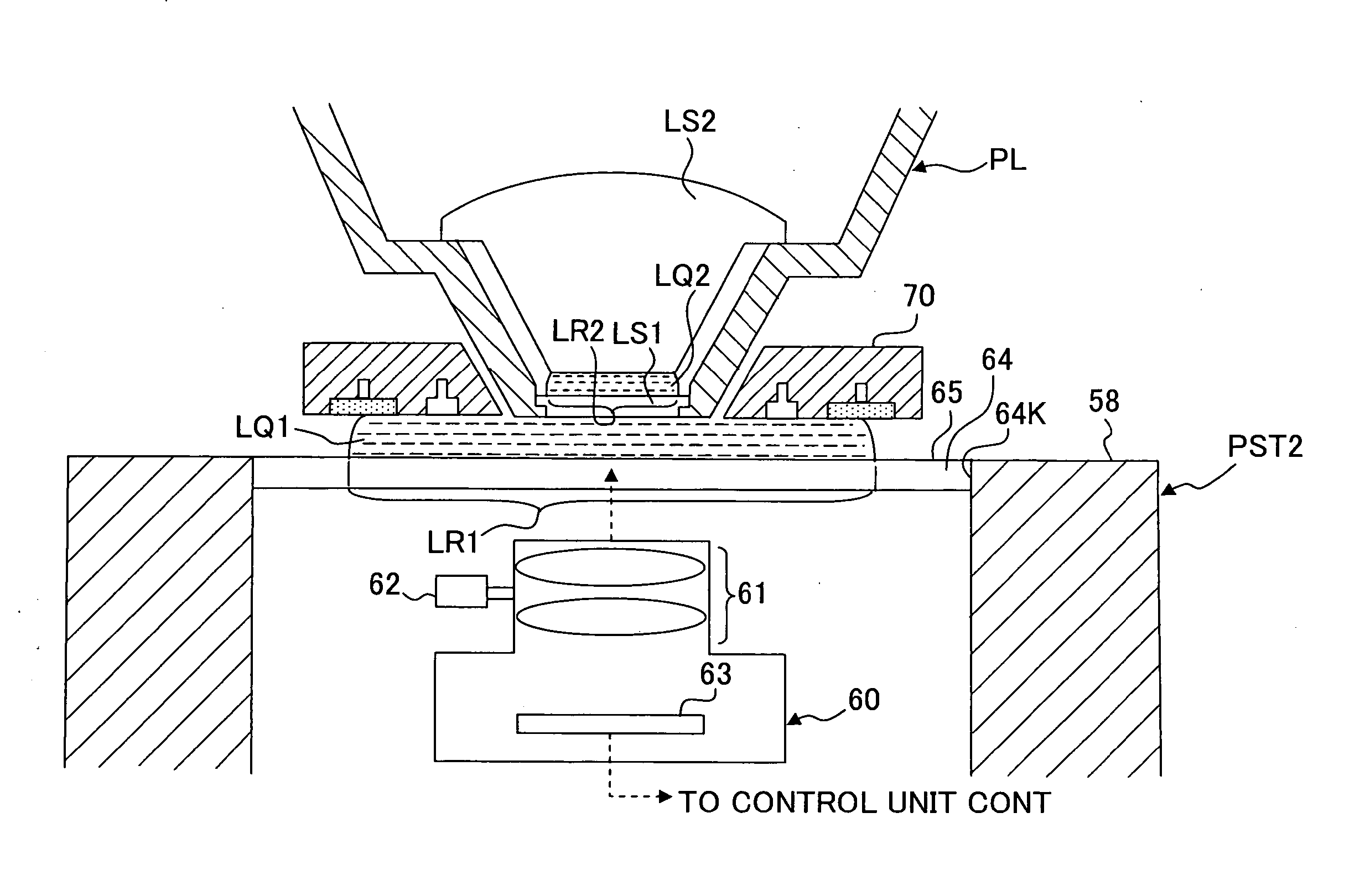
[0101]FIG. 7 is a drawing showing a second embodiment. In the following description, the constitutive parts or portions, which are same or equivalent to those of the first embodiment described above, are designated by the same reference numerals, and any explanation therefor will be simplified or omitted.
[0102] As shown in FIG. 7, when observing the second liquid immersion area LR2 by using the observation unit 60, the control unit CONT may operate to form only the second liquid immersion area LR2 by driving the second liquid immersion mechanism 2 without forming the first liquid immersion area LR1. Also in this case, the observation unit 60 can observe the second liquid immersion area LR2 in the second space K2 via the first optical element LS1.
[0103] The observation of the first liquid immersion area LR1 is executed before or after observation of the second liquid immersion area LR2 in a state that the second liquid immersion area LR2 is formed or the second liquid immersion are...
third embodiment
[0104]FIG. 8 is a drawing of a third embodiment. In FIG. 8, the observation unit 60 is provided in an internal space 66′ of the substrate stage PST1. At a part of the upper surface 51 of the substrate stage PST1, an opening 64K′ is formed so as to be connected to the internal space 66′, and in this opening 64K′, a transparent member 64 is arranged. The transparent member 64 and the observation unit 60 are allowed to be thus provided in the substrate stage PST1 which is movable while holding the substrate P.
[0105] In the above-described embodiments, the observation unit 60 has a field of view larger than the first and second liquid immersion areas LR1 and LR2. However, the observation unit 60 may have a field of view smaller than the first and second liquid immersion areas LR1 and LR2. In this case, by performing observation while moving the measuring stage PST2 (or substrate stage PST1), in which the observation unit 60 is provided, in the XY direction with respect to the projectio...
PUM
 Abstract
Description
Claims
Application Information