Observation device, observation program, and observation system

a technology of observation device and observation program, which is applied in the field of observation device, observation program and observation system, can solve the problems of difficult to observe cell masses with the eye or through a low-magnification microscope, and difficult to find target cell masses and bring them into the view field. , to achieve the effect of reducing the size of the devi

Inactive Publication Date: 2013-06-20
PHC HLDG CORP
View PDF5 Cites 20 Cited by
  • Summary
  • Abstract
  • Description
  • Claims
  • Application Information

AI Technical Summary

Benefits of technology

[0042]According to the present invention, it is possible to provide an observation device that, in observation of a sample such as cells being cultured inside a container, allows identification of a sample mass having occurred by observation of the entire container and in addition allows magnification of the identified sample mass for observation of their details. It is also possible to provide an observation program and an observation system that allow continuous observation of cell masses from their occurrence till completion of their growth.
[0043]Furthermore, for observation of a sample being cultured inside a container, a configuration is adopted where an optical axis of the optical system of an overall observation portion for observation of the entire container and an optical axis of the optical system of a magnified observation portion for observation of the sample through magnification of a partial region within the container coincide with each other, and this makes it possible to greatly reduce the size of the device compared with conventional ones.

Problems solved by technology

However, cell observation using a microscope requires much trouble.
Magnified observation suffers from a narrow view field, and this makes it difficult to find target cell masses and also to bring them into the view field.
Immediately after semination of cells, it is impossible to observe cell masses with the eye or through a low-magnification microscope, and this makes it necessary to search for them and set the observation positions anew after several days.
Moreover, with conventional observation, which is performed about once a day to three days when the culture container is replenished with the culture fluid or the culture fluid is replaced, it is difficult to observe cell masses from their occurrence, and thus there are strong demands for technologies that allow observation of cell masses from their occurrence.
Furthermore, both in observation of an entire container and in observation of part of the inside of a container on a magnified scale, when images of cells are taken, inconveniently, the heat generated by an illuminator and a lens drive system affects the growth of the cells.

Method used


Image

  • Observation device, observation program, and observation system
  • Observation device, observation program, and observation system
  • Observation device, observation program, and observation system

Examples


embodiment 1

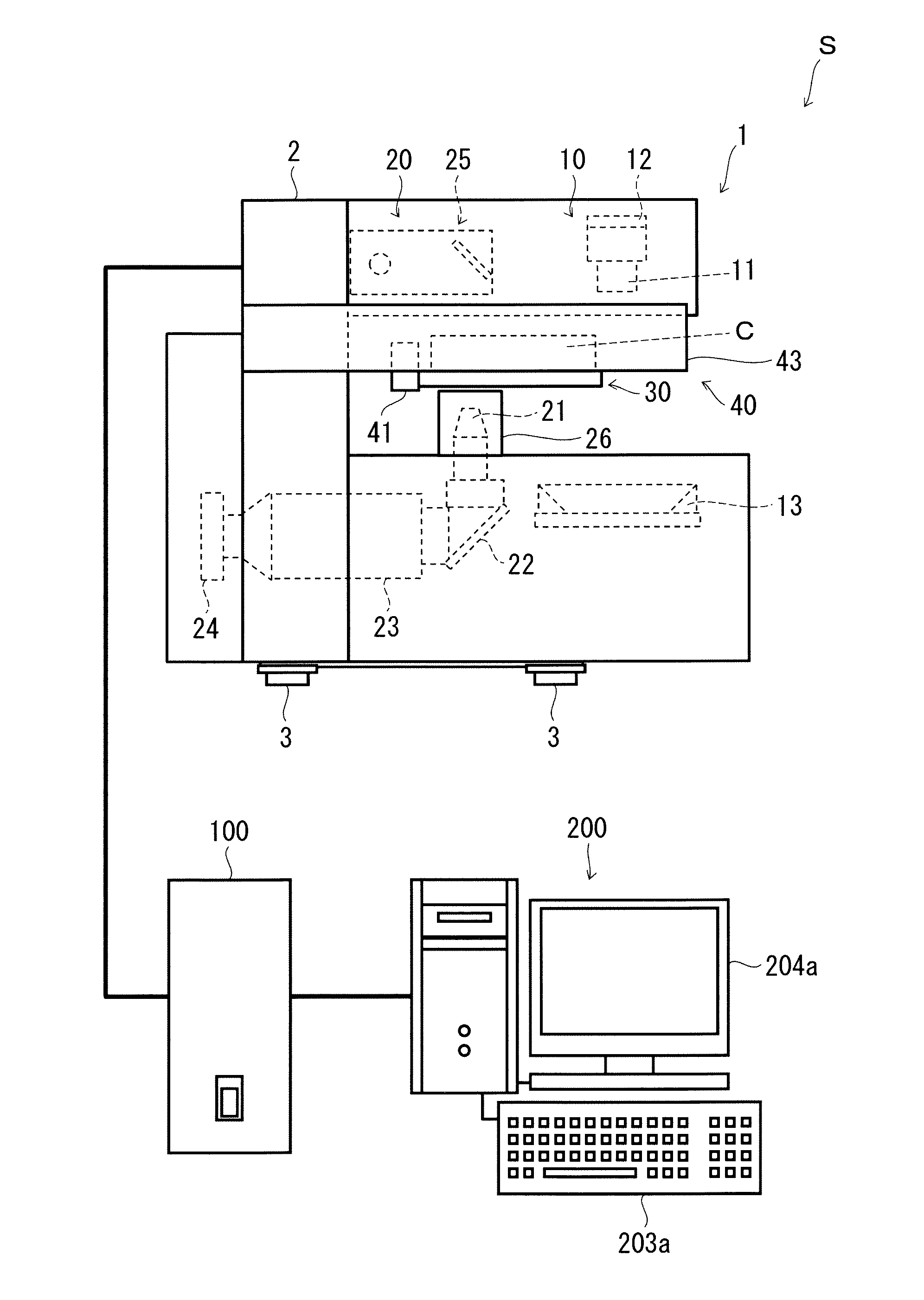
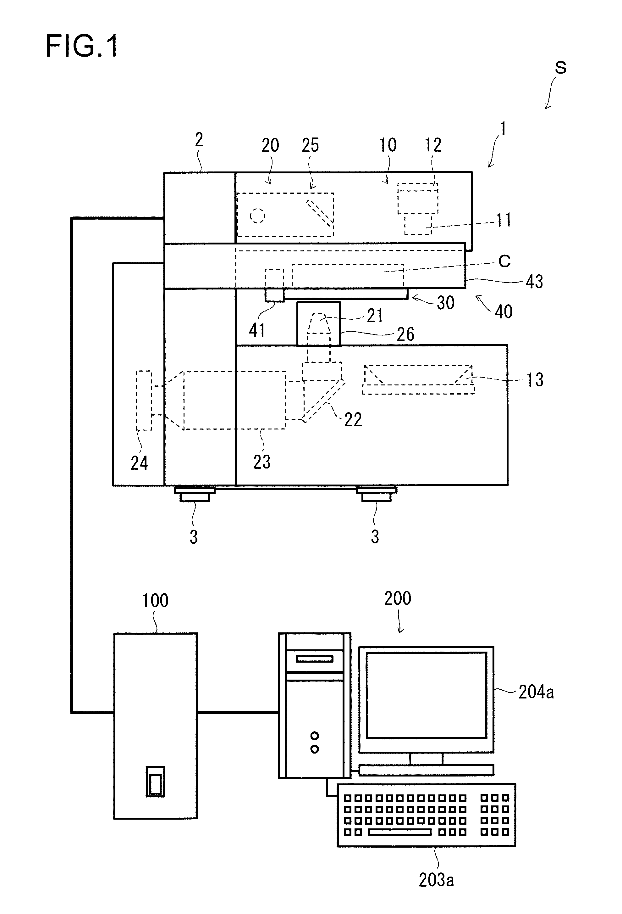
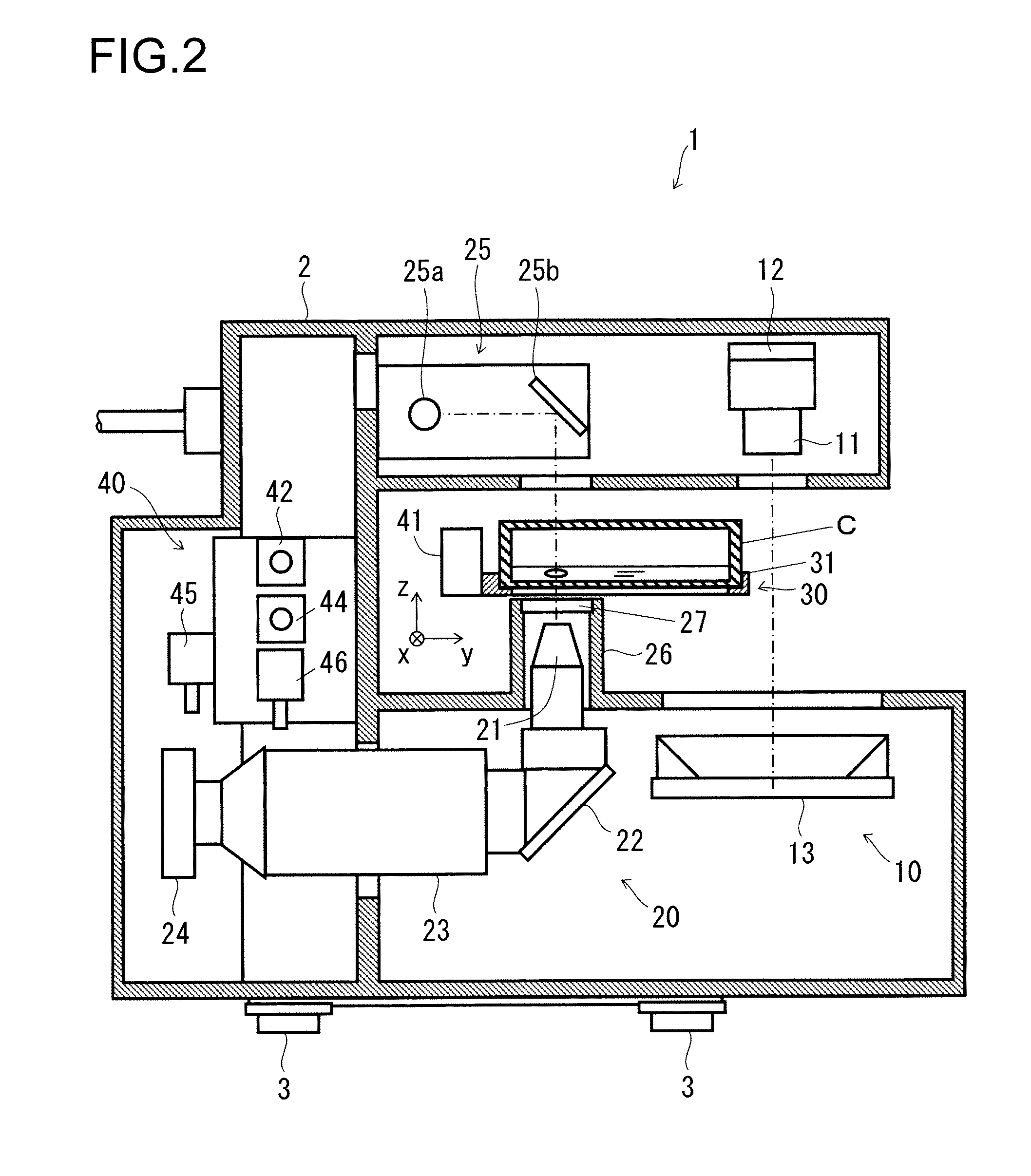
[0060]First, the configuration of an observation system according to a first embodiment of the invention will be described with reference to FIGS. 1 to 5. FIG. 1 is a configuration diagram of the observation system. FIG. 2 is a vertical sectional side view of an observation device in the observation system. FIG. 3 is a vertical sectional front view of the observation device. FIG. 4 is a vertical sectional side view of the observation device, with a container moved to a position corresponding to an overall observation portion. FIG. 5 is a block diagram showing the computer configuration of the observation system. In the following description, the x-axis direction in FIGS. 2 and 3 is referred to as the left / right direction, the y-axis direction there is referred to as the front / rear direction (the +y side being frontward and the −y side being rearward), and the z-axis direction there is referred to as the up / down direction.

[0061]As shown in FIG. 1, the observation system S is provided...

embodiment 2

[0140]Next, with respect to an observation program according to a second embodiment of the invention, operations related to its observation processing will be described along the flow shown in FIG. 8. FIG. 8 is a flow chart showing the operations related to observation processing in the observation program. The configuration in this embodiment is basically the same as that in the first embodiment described previously with reference to FIGS. 1 to 7, and therefore such components as are common to those of the first embodiment will be omitted from illustration and description.

[0141]When the observation program 220 according to the second embodiment is executed (“START” in FIG. 8), it first checks whether or not now is within the predetermined discrimination period (Step #301). If now is within the predetermined discrimination period (“Yes” at Step #301), the observation program 220 instructs the overall observation portion 10 in the observation device 1 to sense the entire container C ...

embodiment 3

[0148]Next, with respect to an observation program according to a third embodiment of the invention, operations related to its observation processing will be described along the flow shown in FIGS. 9 and 10. FIG. 9 is a flow chart showing the operations related to observation processing in the observation program, and FIG. 10 is a continuation of the flow chart shown in FIG. 9 showing the operations related to observation processing. The configuration in this embodiment is basically the same as that in the first and second embodiments described previously, and therefore such components as are common to those of those embodiments will be omitted from illustration and description.

[0149]In the third embodiment, Steps #401 through #410 in the operation flow in FIG. 9 and Steps #411 through #413 in the operation flow in FIG. 10 are the same as in the operation flow in FIGS. 7 and 8, and therefore their description will be omitted.

[0150]The observation program 220 preliminarily sets the c...


PUM


Abstract

An observation device (1) is provided with: a general observation unit (10) for observing sample cells by observing an entire container (C) containing the cells and a culture solution; and a magnification observation unit (20) for magnifying a region within the container (C) and observing the cells, the general observation unit (10) and the magnification observation unit (20) each individually having lighting for illuminating the cells with light, and an optical system for observing the cells. The general observation unit (10) and the magnification observation unit (20) are thereby each provided with an individual optical system and lighting, making it possible to configure an appropriate observation unit for use both when the cells are observed by observing the entire container (C) and when a part within the container (C) is magnified and the cells are observed.

Description

TECHNICAL FIELD[0001]The present invention relates to an observation device, an observation program, and an observation system for observation of a sample such as biological or other cells.BACKGROUND ART[0002]In the culturing of cells, an ability to start observation simultaneously with occurrence of a cell mass, which is a mass of a plurality of cells, and then continue the observation along the time axis can be said to be a promising technology that may assist, for example, regenerative medicine. Conventionally, such observation of cells is performed under a microscope during the culturing of the cells when the culture container needs to be replenished with the culture fluid or the culture fluid needs to be replaced, and images (photos) are taken as necessary.[0003]However, cell observation using a microscope requires much trouble. For example, to identify cell masses that have occurred inside a container, it is necessary first to observe the entire container with the eye or throu...

Claims


Application Information

Patent Timeline
Patent Type & Authority Applications(United States)
IPC IPC(8): A61B5/00
CPCG01N21/13G02B21/0088C12M41/36A61B5/0033G02B21/365H04N23/56G01N21/01G01N2201/022G01N2201/062G01N2201/0638G02B21/361
Inventor HOUJOU, MIKIOODA, ATSUSHI
Owner PHC HLDG CORP
Why Eureka
Try Eureka