
Backlight assembly and method for assembling the same

a backlight and assembly technology, applied in the field of backlight assembly, can solve the problems of poor light uniformity and durability of the direct-illumination backlight assembly, and the difficulty of automatic assembly, and achieve the effect of easy assembly

Inactive Publication Date: 2008-04-10
SAMSUNG ELECTRONICS CO LTD
View PDF3 Cites 28 Cited by
  • Summary
  • Abstract
  • Description
  • Claims
  • Application Information

AI Technical Summary

Benefits of technology

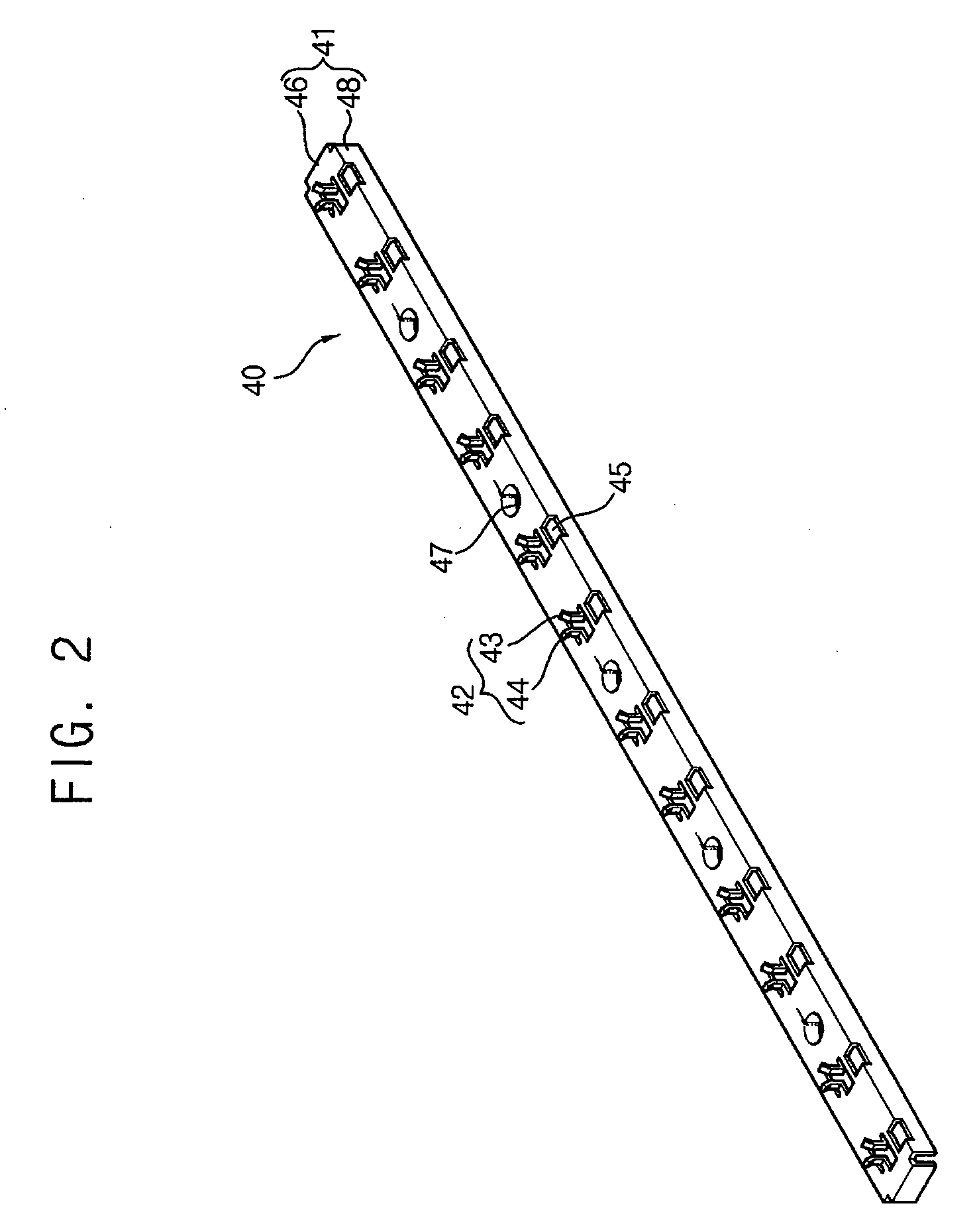
[0010]The present invention provides a backlight assembly that may be automatically assembled by decreasing the number of parts for grounding a plurality of lamps.
[0023]Accordingly, a first electrode of a lamp having less number of parts is grounded to a receiving container via an automatic assembly process, so that the number of parts of a backlight assembly may be decreased and the backlight assembly may be more easily assembled.

Problems solved by technology

The direct-illumination backlight assembly has poorer light uniformity and durability than the edge-illumination type.
In addition, a lamp assembly process, a soldering process, a final assembly process, and so on, are necessary, making automatic assembly difficult.

Method used


Image

  • Backlight assembly and method for assembling the same
  • Backlight assembly and method for assembling the same
  • Backlight assembly and method for assembling the same

Examples


Embodiment Construction

[0046]The invention is described more fully hereinafter with reference to the accompanying drawings, in which embodiments of the invention are shown. In the drawings, the size and relative sizes of layers and regions may be exaggerated for clarity. It will be understood that when an element or layer is referred to as being “on,”“connected to” or “coupled to” another element or layer, it can be directly on, connected or coupled to the other element or layer or intervening elements or layers may be present. In contrast, when an element is referred to as being “directly on,”“directly connected to” or “directly coupled to” another element or layer, there are no intervening elements or layers present.

Backlight Assembly

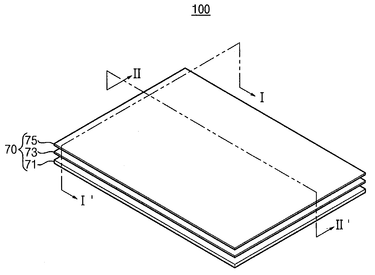
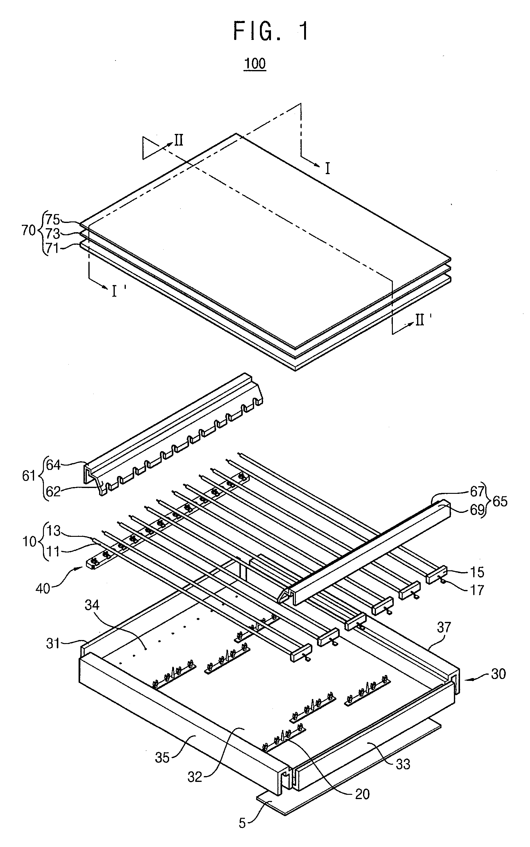
[0047]FIG. 1 is an exploded perspective view illustrating a backlight assembly 100 according to an exemplary embodiment of the present invention.

[0048]Referring to FIG. 1, a backlight assembly 100 according to the present example embodiment of the present invention includes...


PUM


Abstract

A backlight assembly and a method of assembling the backlight assembly that includes a plurality of lamps having first and second electrodes, a receiving container and a lamp ground member. The receiving container has a bottom plate over which the lamps are disposed, and a side wall extending from the bottom plate to form a receiving space. The lamp ground member includes a ground plate grounded to the bottom plate, and a plurality of electrode ground portions protruded from the ground plate and making contact with the first electrode thereby eliminating the need for a separate part for grounding the first electrode of the lamp and permitting easier assembly of the backlight assembly.

Description

CROSS-REFERENCE TO RELATED APPLICATIONS[0001]This application claims priority under 35 U.S.C. § 119 to Korean Patent Application No. 2006-97787, filed on Oct. 9, 2006, and No. 2007-36592, filed on Apr. 13, 2007 in the Korean Intellectual Property Office (KIPO), the contents of which are herein incorporated by reference in their entireties.BACKGROUND OF THE INVENTION[0002]1. Field of the Invention[0003]The present invention relates to a backlight assembly for liquid crystal displays (LCD) and, more particularly, to a backlight assembly that permits improved manufacturing using automatic assembly procedures.[0004]2. Description of the Related Art[0005]Generally, backlight assemblies used for liquid crystal displays are classified as a direct or edge-illumination. A direct-illumination backlight assembly includes a light source located under the liquid crystal panel while an edge-illumination backlight assembly includes a light source that is disposed at one or both sides of a light gu...

Claims


Application Information

Patent Timeline
IPC IPC(8): F21V21/00H01J9/18
CPCG02F1/133608G02F1/133604
Inventor YANG, YONG-SEOKHA, JIN-HOKANG, JUNG-TAE
Owner SAMSUNG ELECTRONICS CO LTD
Learn More