Impact absorbing device

a technology of impact absorption device and disc, which is applied in the direction of engine starter, coupling, slip coupling, etc., can solve the problems of increasing abrasion between the convex portions, unstable slipping torque between the discs, and partially seizing up or burning the surface of the disc, etc., to achieve the effect of reliably absorption of an impact for

Inactive Publication Date: 2008-04-17
DENSO CORP
View PDF5 Cites 12 Cited by
  • Summary
  • Abstract
  • Description
  • Claims
  • Application Information

AI Technical Summary

Benefits of technology

[0011]An object of the present invention is to provide, with due consideration to the drawbacks of the conventional impact absorbing device, an impact absorbing device which reliably absorbs an impact force by a frictional force acting between fixed and rotary discs for a long time while stabilizing a slipping torque of the rotary disc.

Problems solved by technology

This direct contact increases abrasion between the convex portions.
As a result, the frictional surfaces of the discs partially seize up or are burned, and the slipping torque between the discs become unstable so as to change a rotational speed of the rotary discs with time.
Finally, there is a high probability that the rotary discs may be locked due to the seizure of the discs.
In other words, even when a driving torque is excessively transmitted to the rotary discs, the rotary discs cannot be rotated, and the impact absorbing device malfunctions.

Method used


Image

  • Impact absorbing device
  • Impact absorbing device
  • Impact absorbing device

Examples


embodiment 1

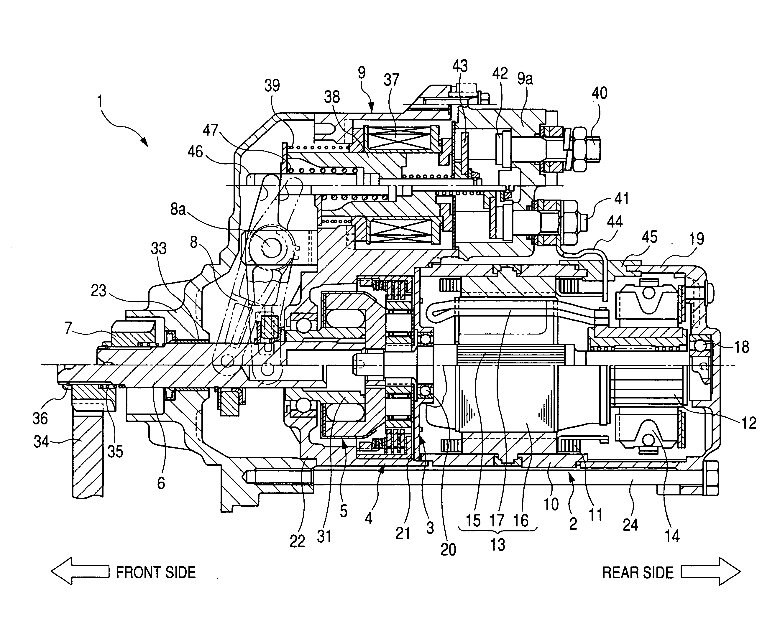
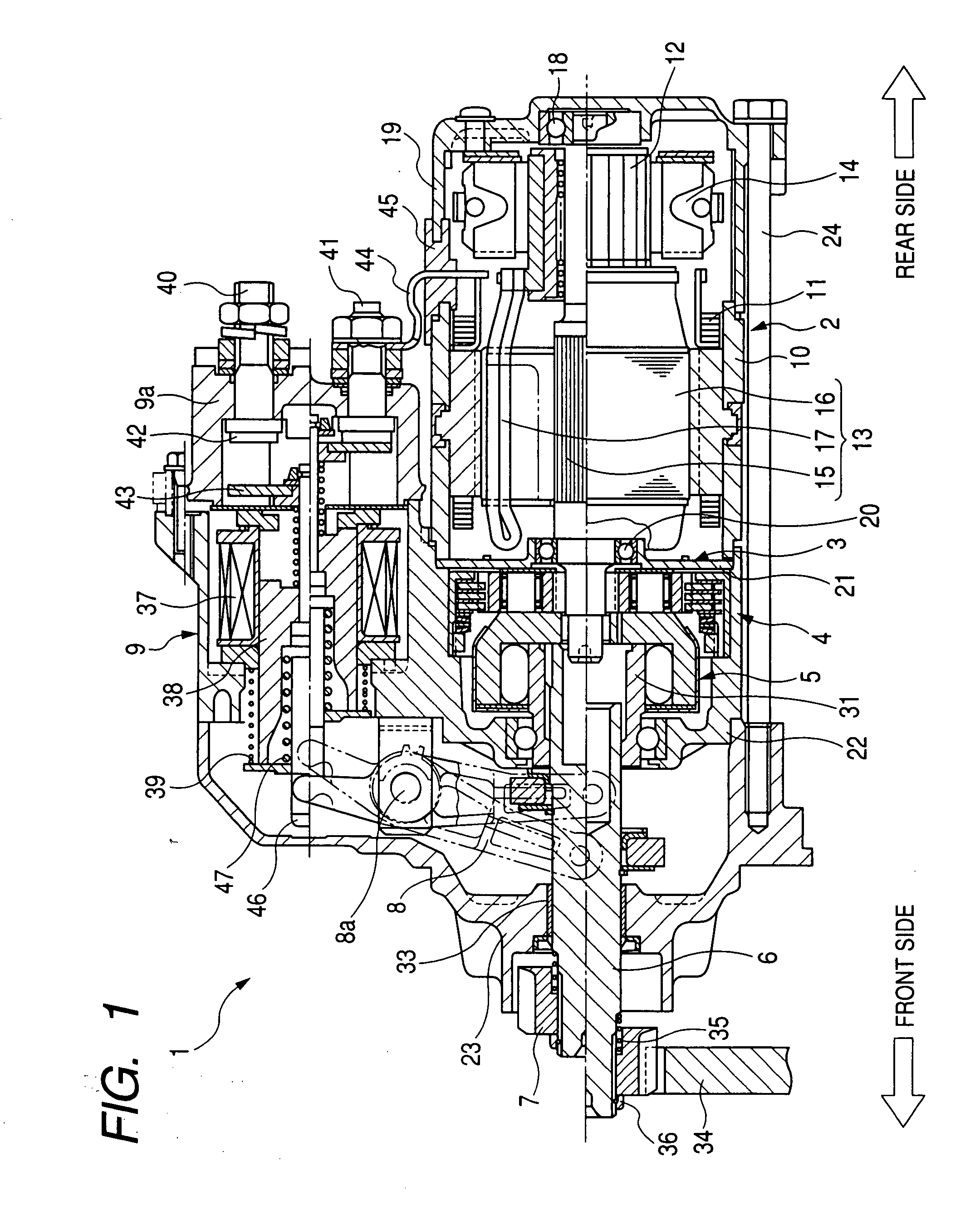
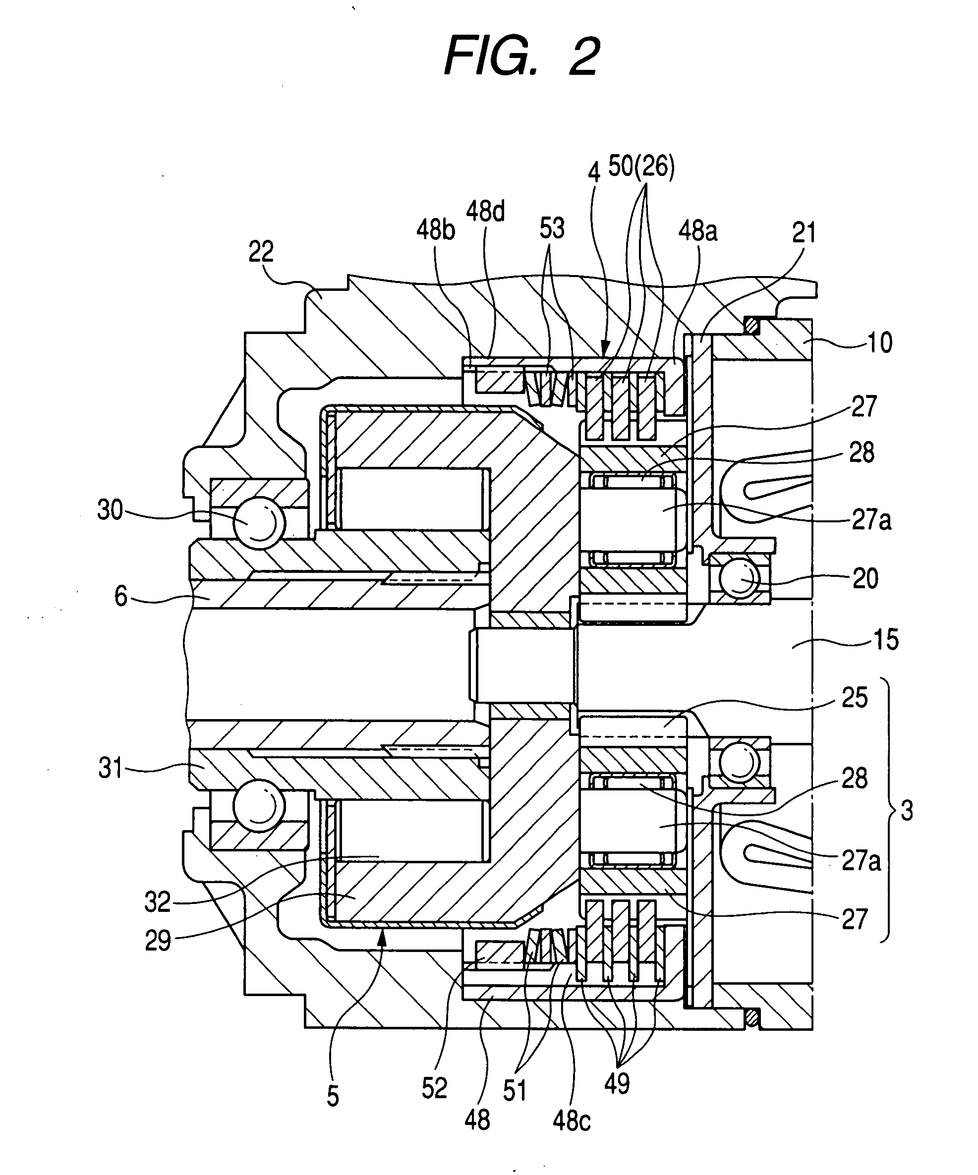
[0042]FIG. 1 is a longitudinal sectional view of a starter with an impact absorbing device according to the first embodiment, while FIG. 2 is an enlarged sectional view of the impact absorbing device, a speed reducer and a clutch of the starter shown in FIG. 1. A starter 1 shown in FIG. 1 starts a driving operation of an internal combustion engine (not shown) of a vehicle.

[0043]As shown in FIG. 1, the starter 1 has a direct current (DC) motor 2 generating a rotational force (i.e., driving torque) at a high rotational speed, a planetary gear type speed reducer 3 reducing the rotational speed of the rotational force transmitted from the motor 2, an impact absorbing device 4 structured in combination with the speed reducer 3, a one-way clutch 5, a pinion shaft 6 connected with the speed reducer 3 through the clutch 5, a pinion gear 7 supported by the pinion shaft 6, and an electromagnetic switch 9 opening and closing a main contact point of an energizing circuit (hereinafter, called a ...

embodiment 2

[0094]In the first embodiment, the dimples 50b of each rotary disc 50 are disposed at the same equal pitch Pd in the radial direction as the dimples 49b of any fixed disc 49 are disposed, and a dimple position in the arranging pattern of the dimples 50b is shifted in the radial direction from a dimple position in the arranging pattern of the dimples 49b. However, the pitch of the dimples 50b in the radial direction may be differentiated from that of the dimples 49b to shift the dimples 50b from the dimples 49b in the radial direction.

[0095]FIG. 9A is a partial plan view of one fixed disc 49 according to the second embodiment, while FIG. 9B is a partial plan view of one rotary disc 50 according to the second embodiment.

[0096]As shown in FIG. 9A and FIG. 9B, the dimples 49b of each fixed disc 49 are regularly disposed in the same manner as in the first embodiment. That is, the dimples 49b are arranged to form a plurality of blocks aligned with one another along the circumferential dir...

embodiment 3

[0102]In the first and second embodiments, the dimples 49b of each block are arranged along the radial direction, and the dimples sob of each block are arranged along the radial direction. However, the dimples sob of each block may be arranged along an aligning direction different from the radial direction, while the dimples 49b of each block are arranged along the radial direction.

[0103]FIG. 10A is a partial plan view of one fixed disc 49 according to the third embodiment, while FIG. 10B is a partial plan view of one rotary disc 50 according to the third embodiment.

[0104]As shown in FIG. 10A and FIG. 10B, the dimples 49b of the fixed discs 49 are disposed on each frictional surface in the same arranging pattern as the dimples 49b of the fixed discs 49 are disposed according to the first embodiment. In contrast, the dimples 50b of each rotary disc 50 are arranged to form a plurality of blocks aligned with one another along a first aligning direction D1 inclined by an angle α (0≦α≦45...


PUM


Abstract

An impact absorbing device has fixed discs and rotary discs alternately and coaxially disposed. Each disc has two surfaces, and two surfaces of each pair of fixed and rotary discs face each other through a lubricant. Each surface has dimples, respectively, surrounded by concave portions. A position of each dimple in the rotary discs is differentiated from a position of any dimple of the fixed discs in a radial direction of the discs. In response to an impact given to the rotary discs, the rotary discs are rotated on the fixed discs against a frictional force between the discs to absorb the impact. During this rotation, each dimple of the rotary discs is moved along a circumferential direction of the discs, and no concave portions of the rotary discs are placed just on the concave portions of the fixed discs.

Description

CROSS-REFERENCE TO RELATED APPLICATION[0001]This application is based upon and claims the benefit of priority of the prior Japanese Patent Application 2006-280014 filed on Oct. 13, 2006 so that the contents of which are incorporated herein by reference.BACKGROUND OF THE INVENTION[0002]1. Field of the Invention[0003]The present invention generally relates to a multiple disc type impact absorbing device which absorbs an impact generated when a starter starts a driving operation of an engine.[0004]2. Description of Related Art[0005]When a starter starts a driving operation of an internal combustion engine, a driving torque of a motor is transmitted from an armature shaft to a ring gear of the engine through a pinion gear to crank the engine. At the cranking time of the engine, an impact force caused by a collision of the pinion gear with the ring gear is generated in the pinion gear and is transmitted to the armature shaft through a speed reducer. The starter has an impact absorbing de...

Claims


Application Information

Patent Timeline
Patent Type & Authority Applications(United States)
IPC IPC(8): F02N15/02
CPCF02N15/046F02N15/063Y10T74/137Y10T74/13Y10T74/134
Inventor NAWA, YUKIO
Owner DENSO CORP
Why Eureka
Try Eureka