Optical disc apparatus, focus position control method and optical disc

a technology of optical discs and control methods, applied in the direction of digital signal error detection/correction, instruments, recording signal processing, etc., can solve the problems of not being able to accurately, not being able to properly record information on and reproduce information from the optical discs, and not being able to accommodate the surface shake and decentering of the optical discs

Inactive Publication Date: 2008-04-17
SONY CORP
View PDF4 Cites 17 Cited by
  • Summary
  • Abstract
  • Description
  • Claims
  • Application Information

AI Technical Summary

Benefits of technology

[0021] While conventional optical disc apparatus adapted to CDs, DVDs and BDs can give rise to surface shakes and decenterings of the optical disc being driven to rotate, they can accurately irradiate a light beam onto the target track of the optical disc by way of various control operations including focusing control and tracking control on the basis of the outcome of detection of the light beam.

Problems solved by technology

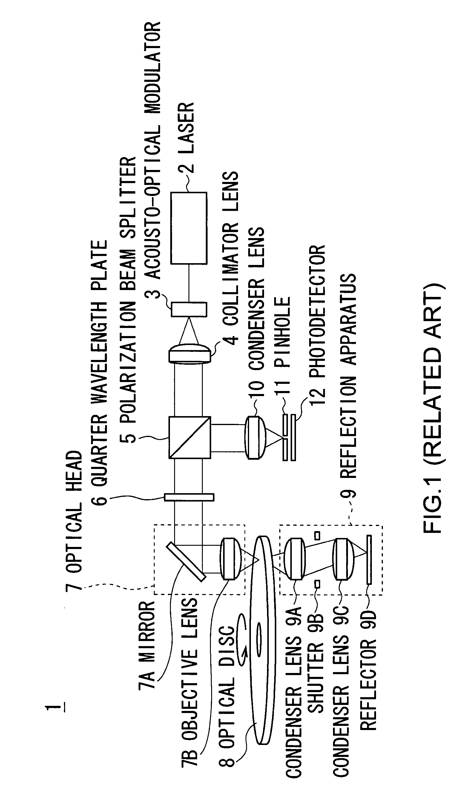
However, the optical disc apparatus 1 illustrated in FIG. 1 is not designed to perform control operations including focusing control and tracking control and hence it is not able to accommodate itself to surface shakes and decenterings that arise to the optical disc.
In other words, the optical disc apparatus 1 does not able to accurately align the focus of the light beam with the desired position in the optical disc 8 and hence may not be able to properly record information on and reproduce information from the optical disc.

Method used


Image

  • Optical disc apparatus, focus position control method and optical disc
  • Optical disc apparatus, focus position control method and optical disc
  • Optical disc apparatus, focus position control method and optical disc

Examples


Embodiment Construction

[0058] Now, embodiments of the present invention will be described in greater detail by referring to the accompanying drawings.

(1) Configuration of Optical Disc

[0059] Firstly, an optical disc 100 to be used as information recording medium according to the present invention will be described. FIG. 3A is a schematic illustration of the optical disc 100, showing the appearance thereof. Referring to FIG. 3A, the optical disc 100 has a diameter of about 120 mm and a hole section 100H is formed at the center thereof like conventional CDs, DVDs and BDs.

[0060] As seen from FIG. 3B showing a cross sectional view of the optical disc 100, the optical disc 100 has a recording layer 101 for recording information at the middle thereof, which recording layer 101 is sandwiched by substrates 102 and 103 from the opposite surfaces thereof.

[0061] Note that the recording layer 101 has a thickness t1 of about 0.3 mm and the substrates 102 and 103 have respective thicknesses t2 and t3 that are about ...


PUM

PropertyMeasurementUnit
diameteraaaaaaaaaa
refractive indexaaaaaaaaaa

Abstract

An optical disc apparatus and a focus position control method can highly accurately record recording marks representing information on or reproduce such recording marks from an optical disc. A blue light beam is irradiated onto the target depth to be irradiated by driving an objective lens to focus a red light beam in a reflection / transmission film formed in the optical disc and displacing a movable lens, which is a focus moving section, of a relay lens. A blue light reflection region is formed as part of the reflection / transmission film and the position of the blue light reflection region where the red light focus and the blue light focus are aligned is defined as reference position. The movable lens is displaced by an arbitrarily selected quantity from the reference position according to the target depth.

Description

CROSS REFERENCE TO RELATED APPLICATIONS [0001] The present invention contains subject matter related to Japanese Patent Application JP 2006-277875 filed in the Japanese Patent Office on Oct. 11, 2006, the entire contents of which being incorporated herein by reference. BACKGROUND OF THE INVENTION [0002] 1. Field of the Invention [0003] This invention relates to an optical disc apparatus, a focus position control method and an optical disc that can suitably find applications in the field of optical disc apparatus for recording holograms on optical discs. [0004] 2. Description of the Related Art [0005] An optical disc apparatus for irradiating a light beam onto an optical disc such as a Compact Disc (CD), a Digital Versatile Disc (DVD) or a Blu-ray disc (trademark, to be referred to as BD herein after) and reproducing information by reading light reflected from the optical disc have become highly popular. [0006] Such optical disc apparatus can also record information on an optical dis...

Claims


Application Information

Patent Timeline
Patent Type & Authority Applications(United States)
IPC IPC(8): G11B7/135
CPCG11B7/0065G11B7/00781G11B7/083G11B7/24044G11B7/0909G11B7/0917G11B7/24G11B7/0901
Inventor MIYAMOTO, HIROTAKASAITO, KIMIHIRO
Owner SONY CORP
Why Eureka
Try Eureka