Method and apparatus for encoding and decoding multi-view video signal, and related computer programs

a multi-view video and signal technology, applied in signal generators with optical-mechanical scanning, color television with bandwidth reduction, television systems, etc., can solve problems such as difficult to know and conceivable system cannot utilize disparity-compensated prediction

Active Publication Date: 2008-04-17
ADVANCED CODING TECH LLC
View PDF2 Cites 136 Cited by
  • Summary
  • Abstract
  • Description
  • Claims
  • Application Information

AI Technical Summary

Problems solved by technology

In the parallel-processing-based decoding in the conceivable system, it is difficult to know, at the time of decoding a coded picture of a viewpoint, whether or not the decoding of a coded picture of another viewpoint to obtain a related reference picture has been completed.
Therefore, the conceivable system can not utilize disparity-compensated prediction.

Method used


Image

  • Method and apparatus for encoding and decoding multi-view video signal, and related computer programs
  • Method and apparatus for encoding and decoding multi-view video signal, and related computer programs
  • Method and apparatus for encoding and decoding multi-view video signal, and related computer programs

Examples


first embodiment

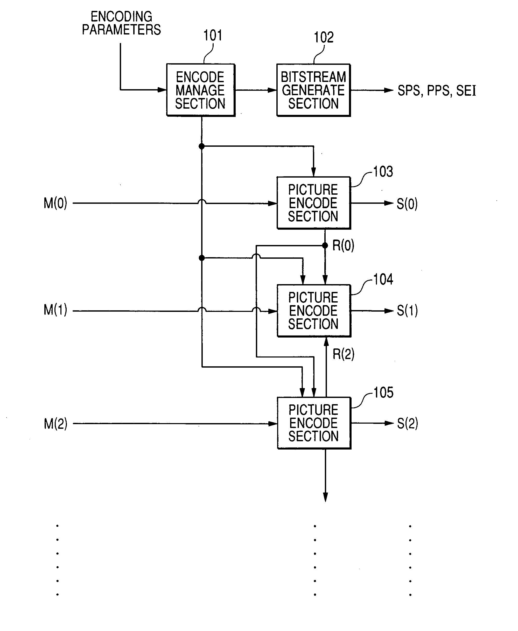
[0058]FIG. 1 shows a multi-view video encoding apparatus according to a first embodiment of this invention. The encoding apparatus of FIG. 1 is extended from an encoding apparatus conforming to the MPEG-4 AVC / H.264 standards. Thus, the encoding apparatus of FIG. 1 has a basic portion designed to conform to the MPEG-4 AVC / H.264 standards.

[0059]As shown in FIG. 1, the encoding apparatus includes an encoding management section 101, a coded bitstream generating section 102, and picture encoding sections 103, 104, and 105. The encoding apparatus may include four or more picture encoding sections.

[0060]There are signals M(v) representing sequences of pictures taken from different viewpoints respectively, which compose a multi-view video sequence, where “v” denotes an ID for each viewpoint, and v=0, 1, 2, . . . . For example, there are data or a signal M(0) representing a sequence of pictures taken from a viewpoint having an ID of v=0, data or a signal M(1) representing a sequence of pictu...

second embodiment

[0125]FIG. 10 shows a multi-view video encoding apparatus according to a second embodiment of this invention. The encoding apparatus of FIG. 10 is similar to that of FIG. 1 except for design changes mentioned hereafter.

[0126]The encoding apparatus of FIG. 10 includes a computer system 10 having a combination of an input / output port 10A, a CPU 10B, a ROM 10C, and a RAM 10D. The input / output port 10A in the computer system 10 receives the encoding parameters and the video sequences M(O), M(1), and M(2). The computer system 10 processes the video sequences M(O), M(1), and M(2) into the coded bitstreams S(0), S(1), and S(2) respectively. The computer system 10 generates the coded bitstream inclusive of SPS, PPS, and SEI. The input / output port 10A outputs the coded bitstreams S(0), S(1), and S(2), and the coded bitstream inclusive of SPS, PPS, and SEI. The computer system 10 (the CPU 10B) operates in accordance with a control program, that is, a computer program stored in the ROM 10C or ...

third embodiment

[0143]FIG. 12 shows a multi-view video decoding apparatus according to a third embodiment of this invention. The decoding apparatus receives the coded bitstream inclusive of SPS, PPS, and SEI, and the different-viewpoint coded bitstreams S(v) from the encoding apparatus of FIG. 1 or FIG. 10, where “v” denotes an ID for each viewpoint, and v=0, 1, 2, . . . . The decoding apparatus decodes the coded bitstream inclusive of SPS, PPS, and SEI. Furthermore, the decoding apparatus decodes the different-viewpoint coded bitstreams S(v) into different-viewpoint decoded video sequences M(v)A.

[0144]The decoding apparatus of FIG. 12 is extended from a decoding apparatus conforming to the MPEG-4 AVC / H.264 standards. Thus, the decoding apparatus of FIG. 12 has a basic portion designed to conform to the MPEG-4 AVC / H.264 standards.

[0145]As shown in FIG. 12, the decoding apparatus includes coded-bitstream decoding sections 301, 303, 306, and 309, a decoding management section 302, buffers (buffer mem...


PUM


Abstract

A multi-view video signal is encoded. The multi-view video signal includes picture signals corresponding to different viewpoints respectively. One among the viewpoints is designated as a base viewpoint. The base viewpoint corresponds to a picture signal which is encoded without referring to at least one picture signal corresponding to one of the viewpoints except the base viewpoint. There is determined a desired delay time of the start of decoding a coded signal originating from each of the picture signals corresponding to the viewpoints except the base viewpoint relative to the start of decoding a coded signal originating from the picture signal corresponding to the base viewpoint. Information representing the determined delay time is generated. Then, the generated information is encoded.

Description

BACKGROUND OF THE INVENTION[0001]1. Field of the Invention[0002]This invention relates to a method, an apparatus, and a computer program for encoding signals representative of multi-view video taken from multiple viewpoints. In addition, this invention relates to a method, an apparatus, and a computer program for decoding coded data representative of multi-view video taken from multiple viewpoints.[0003]2. Description of the Related Art[0004]An MPEG (Moving Picture Experts Group) encoder compressively encodes a digital signal (data) representing a video sequence. The MPEG encoder performs motion-compensated prediction and orthogonal transform with respect to the video signal to implement highly efficient encoding and data compression. The motion-compensated prediction utilizes a temporal redundancy in the video signal for the data compression. The orthogonal transform utilizes a spatial redundancy in the video signal for the data compression. Specifically, the orthogonal transform i...

Claims


Application Information

Patent Timeline
Patent Type & Authority Applications(United States)
IPC IPC(8): H04N7/24H04N19/102H04N19/105H04N19/109H04N19/134H04N19/169H04N19/174H04N19/46H04N19/463H04N19/50H04N19/503H04N19/51H04N19/517H04N19/577H04N19/597H04N19/60H04N19/61H04N19/70H04N19/85H04N19/91
CPCH04N19/597H04N19/577H04N19/573H04N19/51
Inventor NAKAMURA, HIROYAUEDA, MOTOHARU
Owner ADVANCED CODING TECH LLC
Why Eureka
Try Eureka