Radio Base Station, Radio Line Control Station, And Mobile Communication System, And Mobile Communication Method

a radio base station and radio line control technology, applied in the direction of amplitude demodulation, receiver specific arrangement, content conversion, etc., can solve the problems of increasing the size of the apparatus, reducing the number of mobile stations connectable to the radio base station, and increasing the need for buffer capacity

a radio base station and radio line control technology, applied in the direction of amplitude demodulation, receiver specific arrangement, content conversion, etc., can solve the problems of increasing the size of the apparatus, reducing the number of mobile stations connectable to the radio base station, and increasing the need for buffer capacity

US20080089447A1Inactive Publication Date: 2008-04-17NTT DOCOMO INC

Image

  • Radio Base Station, Radio Line Control Station, And Mobile Communication System, And Mobile Communication Method
  • Radio Base Station, Radio Line Control Station, And Mobile Communication System, And Mobile Communication Method
  • Radio Base Station, Radio Line Control Station, And Mobile Communication System, And Mobile Communication Method

Examples


Embodiment Construction

[Mobile Communication System]

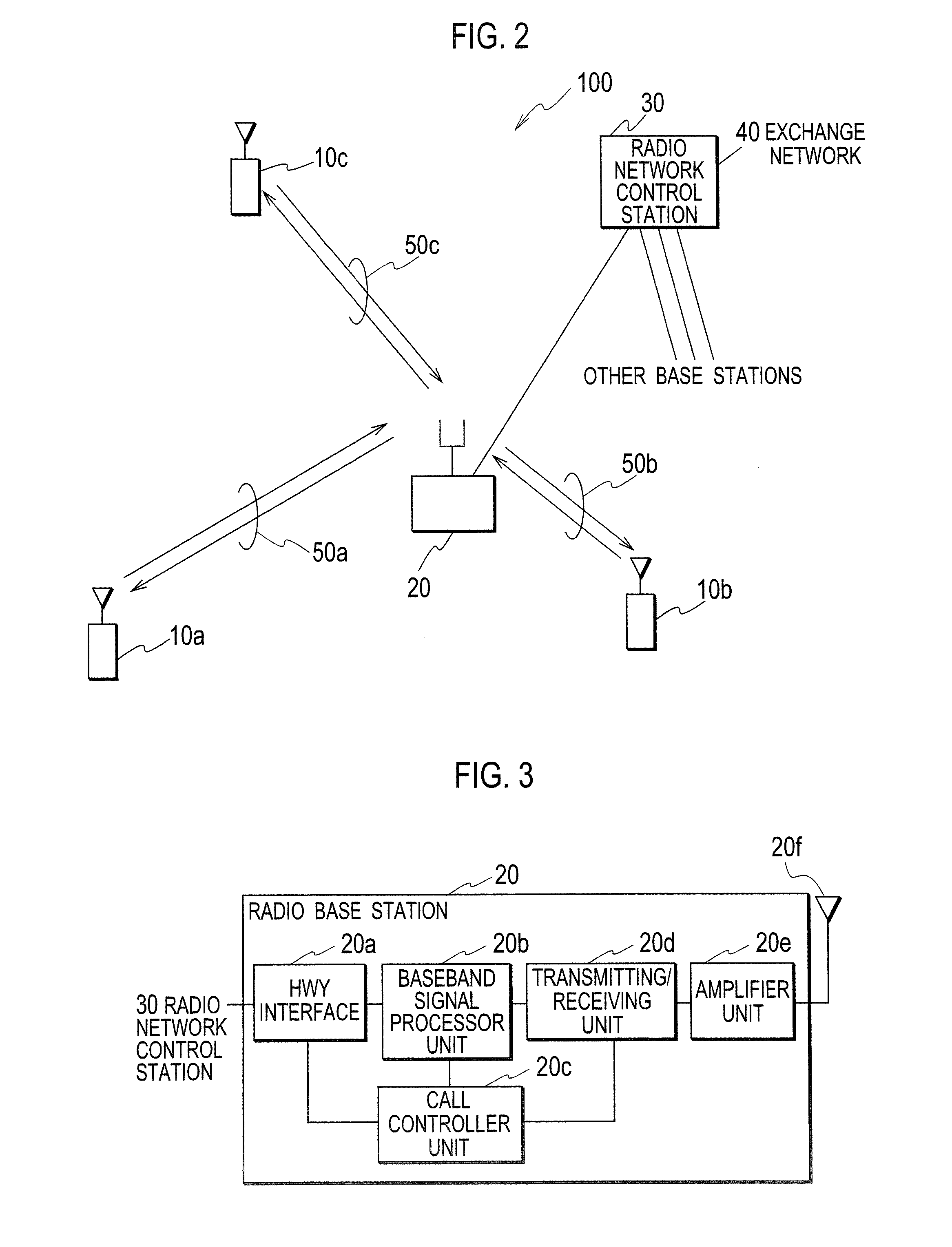
[0036] As shown in FIG. 2, a mobile communication system 100 includes a plurality of mobile stations 10a, 10b and 10c, a radio base station 20, a radio network control station 30, and an exchange network 40. The mobile communication system 100 uses the CDMA (Code Division Multiple Access) as a radio access method between the mobile stations 10a to 10c and the radio base station 20.

[0037] The mobile stations 10a to 10c transmit / receive user data and control data to / from the radio base station 20 by use of radio channels 50a to 50c, respectively. The radio channels have uplink channels to transmit data from the mobile stations 10a to 10c to the radio base station 20; and downlink channels to transmit data from the radio base station 20 to the mobile stations 10a to 10c. Moreover, the radio channels have a dedicated channel dedicated for each of mobile stations 10a to 10c; and a common channel common to the plurality of mobile stations 10a to 10c.

[0038] ...


PUM


Abstract

A radio base station related to the present invention includes: a signal storing unit configured to store baseband signals received and over-sampled; a format determining unit configured to determine transport formats of the baseband signals; and a despreader unit configured to despread the baseband signals stored in the signal storing unit, in accordance with the transport formats determined by the format determining unit, after the determination by the format determining unit.

Description

TECHNICAL FIELD [0001] The present invention relates to a radio base station, a radio network control station, a mobile communication system, and a mobile communication method. BACKGROUND ART [0002] A mobile communication system using CDMA (Code Division Multiple Access) as a radio access method is configured to transmit information with a lower bit rate than that at a time when there is voice or no information, at a time of no voice, so as to decrease interference and to improve the capacity of a radio channel in an uplink for voice communication. [0003] Additionally, the mobile communication system is configured to transmit only transmission data of a mobile station in a case where the transmission data is small in volume, or not to transmit data except a control bit and a pilot bit in an interval when a data transmission is not performed, so as to decrease interference and to improve the capacity of a radio channel in an uplink for data communication as well. [0004] Specifically,...

Claims


Application Information

Patent Timeline
17 Apr 2008
Publication
US20080089447A1
IPC
H04B1/69; H04B1/707; H04W4/18; H04W88/08
CPC
H04B1/707; H04B2201/70703; H04W88/08; H04L1/0039; H04W4/18; H04B2201/70707; H04B1/7115
Inventors
USUDA, MASAFUMI; UMESH, ANIL