

Tapered roller bearing device
a tapered roller bearing and roller bearing technology, which is applied in the direction of roller bearings, mechanical equipment, machines/engines, etc., can solve the problems of insufficient oil supply, increased torque of bearings, and insufficient lubrication in the sliding region, so as to reduce the sliding surface of the large rib portion and reduce the oil agitation loss of the tapered roller bearing device. , the effect of reducing the loss of oil agitation
- Summary
- Abstract
- Description
- Claims
- Application Information
AI Technical Summary
Benefits of technology
Problems solved by technology
Method used
Image

Examples
first embodiment
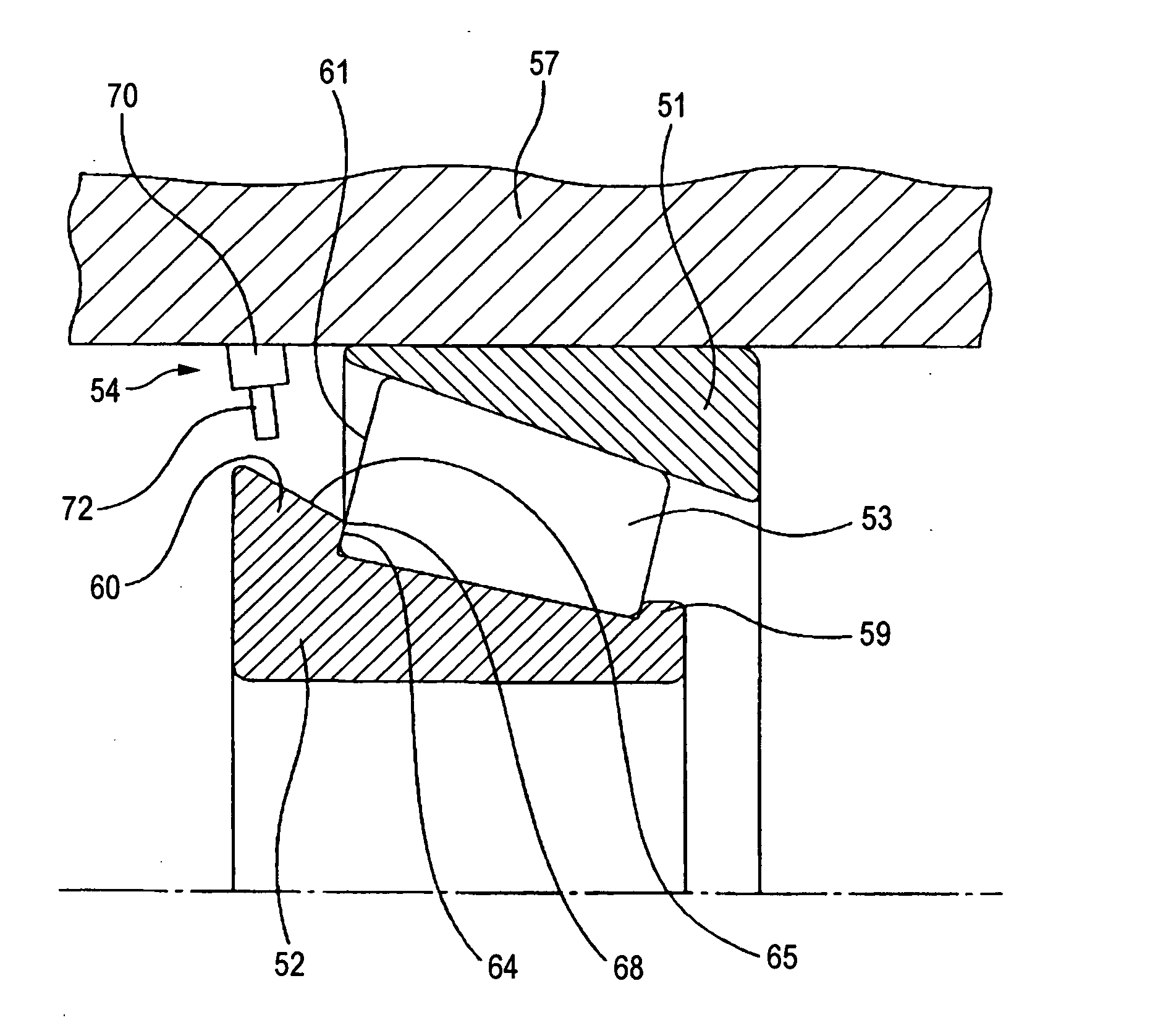
[0048]FIG. 1 is a schematic sectional view of a tapered roller bearing device according to the first embodiment of the invention taken along the axial direction thereof.
[0049] The tapered roller bearing device rotatably supports a pinion shaft 10 of a differential gear system. The tapered roller bearing device includes an outer ring 1, an inner ring 2, tapered rollers 3, a vertical wall member 5 as a projecting portion of the invention and an oil supplying unit 6.
[0050] The outer ring 1 includes a tapered (or conical) raceway surface (outer ring tapered raceway surface) on its inner peripheral side. An outer peripheral surface of the outer ring 1 is internally fitted and fixed to a housing 4 of the differential gear system.
[0051] The inner ring 2 includes a tapered (or conical) raceway surface (inner ring tapered raceway surface) on its outer peripheral side. An inner peripheral surface of the inner ring 2 is externally fitted and fixed to the pinion shaft 10 of the differential ...
second embodiment
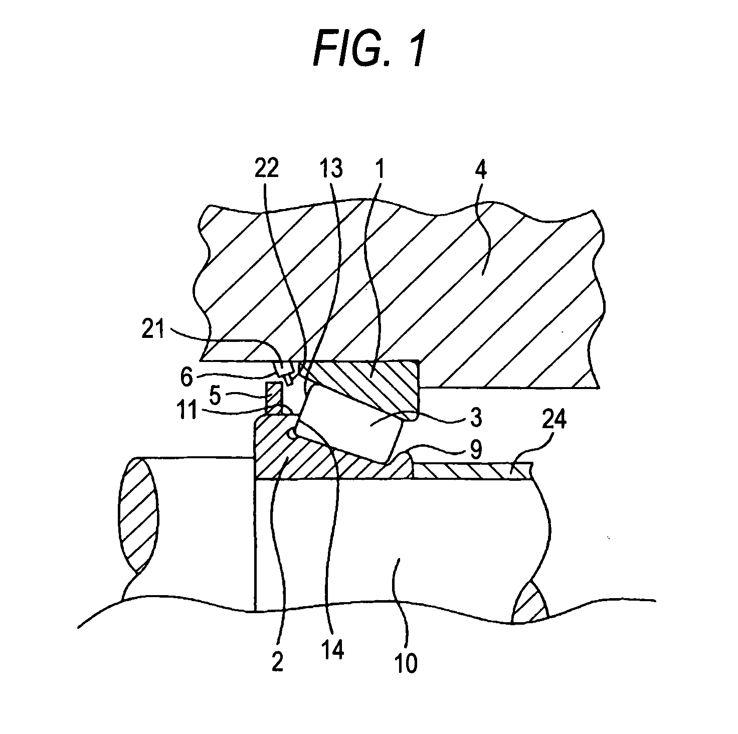
[0070]FIG. 2 is a schematic sectional view of a tapered roller bearing device according to the second embodiment of the invention taken along the axial direction thereof.
[0071] The tapered roller bearing device according to the second embodiment rotatably supports a pinion shaft (not shown) of a differential gear system. The tapered roller bearing device includes an outer ring 51, an inner ring 52, tapered rollers 53 and an oil supplying unit 54.
[0072] The outer ring 51 includes a tapered (or conical) raceway surface (outer ring tapered raceway surface) on its inner peripheral side. An outer peripheral surface of the outer ring 51 is internally fitted and fixed to a housing 57 of the differential gear system. On the other hand, the inner ring 52 includes a tapered (or conical) raceway surface (inner ring tapered raceway surface) on its outer peripheral side. An inner peripheral surface of the inner ring 52 is externally fitted and fixed to the pinion shaft (not shown) of the diffe...
third embodiment
[0091]FIG. 3 is a schematic sectional view of a tapered roller bearing device according to third embodiment of the invention taken along the axial direction thereof.
[0092] In FIG. 3, the reference numeral 140 denotes a cage. The cage 140 includes a tapered (conical) main body portion 141 and a radial extended portion 142. The main body portion 141 has pockets for accommodating tapered rollers 103. The radial extended portion 142 is continuous to a smaller diameter side of the main body portion 141 and is bent radially inwardly so as to extend toward the radial inner direction.
[0093] The tapered roller bearing device has a structure to drop the oil in the radial inner direction of an outer ring 101 directly from an oil dropping portion 104a, which is defined at one of the openings of an oil supply passage 104 formed in a housing 107 as an outer ring fixing member to which the outer ring 101 is fixed onto an outer peripheral tapered surface 115 of a large rib portion 110 of an inner...
PUM
 Abstract
Description
Claims
Application Information