
Method for selective laser crystallization and display panel fabricated by using the same

a laser crystallization and display panel technology, applied in the direction of basic electric elements, electrical equipment, semiconductor devices, etc., can solve the problems of low display resolution, inability to maintain the brightness of the lightening pixel of the pmoled, complex process electrical characteristics, etc., to improve the electrical uniformity of the circuit driving region and increase throughput

Active Publication Date: 2008-04-17
XIAMEN TIANMA DISPLAY TECH CO LTD
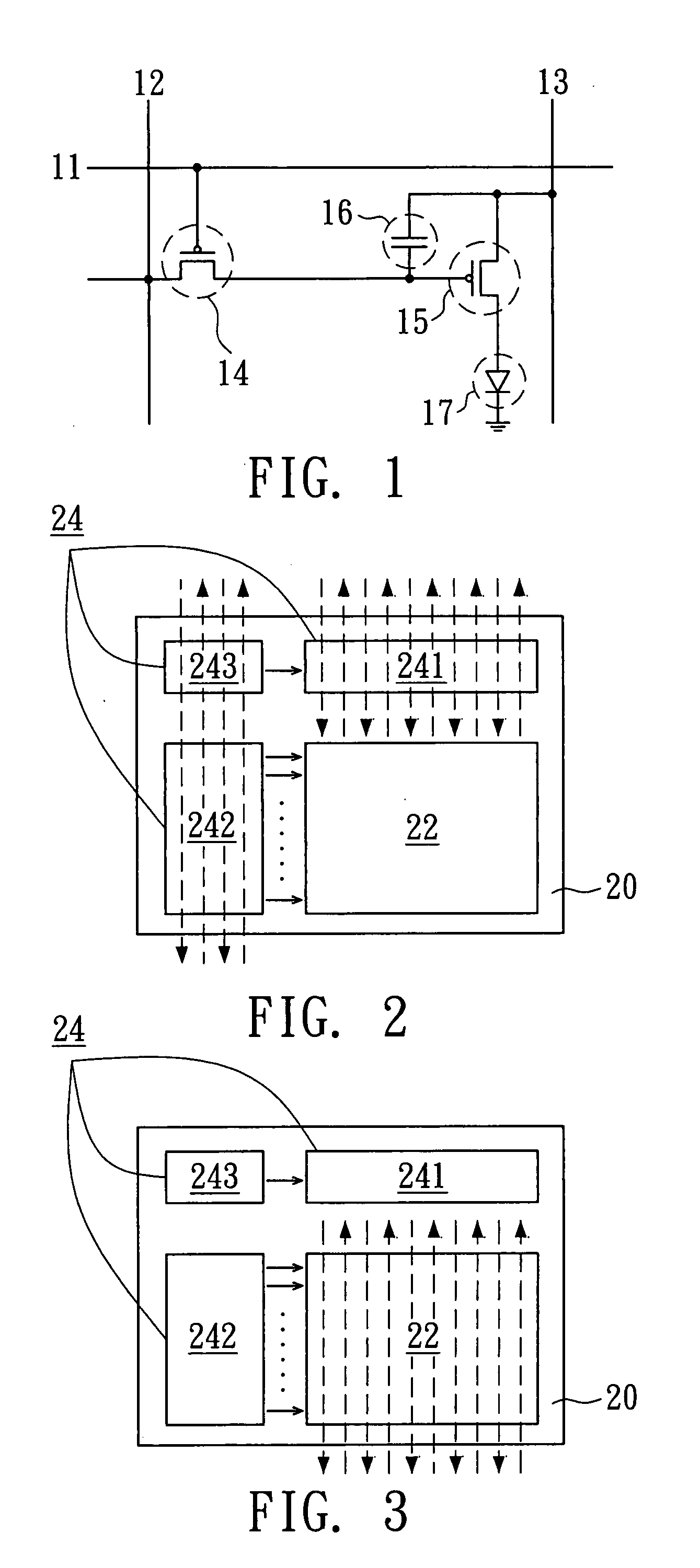
View PDF9 Cites 4 Cited by
  • Summary
  • Abstract
  • Description
  • Claims
  • Application Information

AI Technical Summary

Benefits of technology

[0012] It is therefore an object of the invention to a method for selective laser crystallization and display panel fabricated by using the same, so as to improve the electrical uniformity of the circuit driving region of the display panel and to increase the throughput.

Problems solved by technology

Generally, the PMOLED has the advantages of low production cost and simple technique, but the inefficient drive current results in the low resolution of the display.
Also, the brightness of the lighten pixel of the PMOLED cannot be well maintained.
The major differences between the a-Si process and the LTPS process are the electrical characteristics of devices and the complexity of processes.
The LTPS TFT possesses higher mobility, but the process for fabricating the LTPS TFT is more complicated.
However, the polysilicon formed by the excimer laser beam has the irregular grain size and grain boundary, resulting in non-uniform electrical characteristics of the TFTs for driving the displaying region while the operating voltage is applied.
Therefore, the image defects such as dark spot defects and dark line defects could be shown on the displaying region during displaying.

Method used


Image

  • Method for selective laser crystallization and display panel fabricated by using the same
  • Method for selective laser crystallization and display panel fabricated by using the same
  • Method for selective laser crystallization and display panel fabricated by using the same

Examples


Embodiment Construction

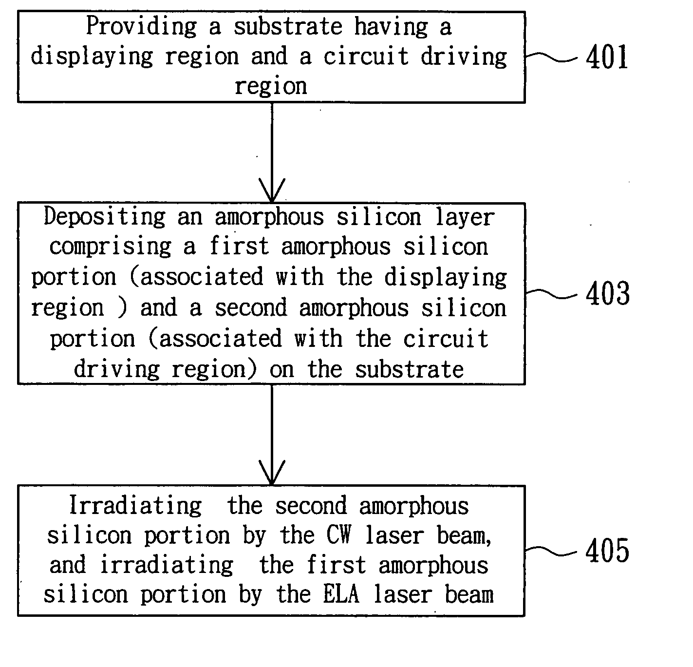
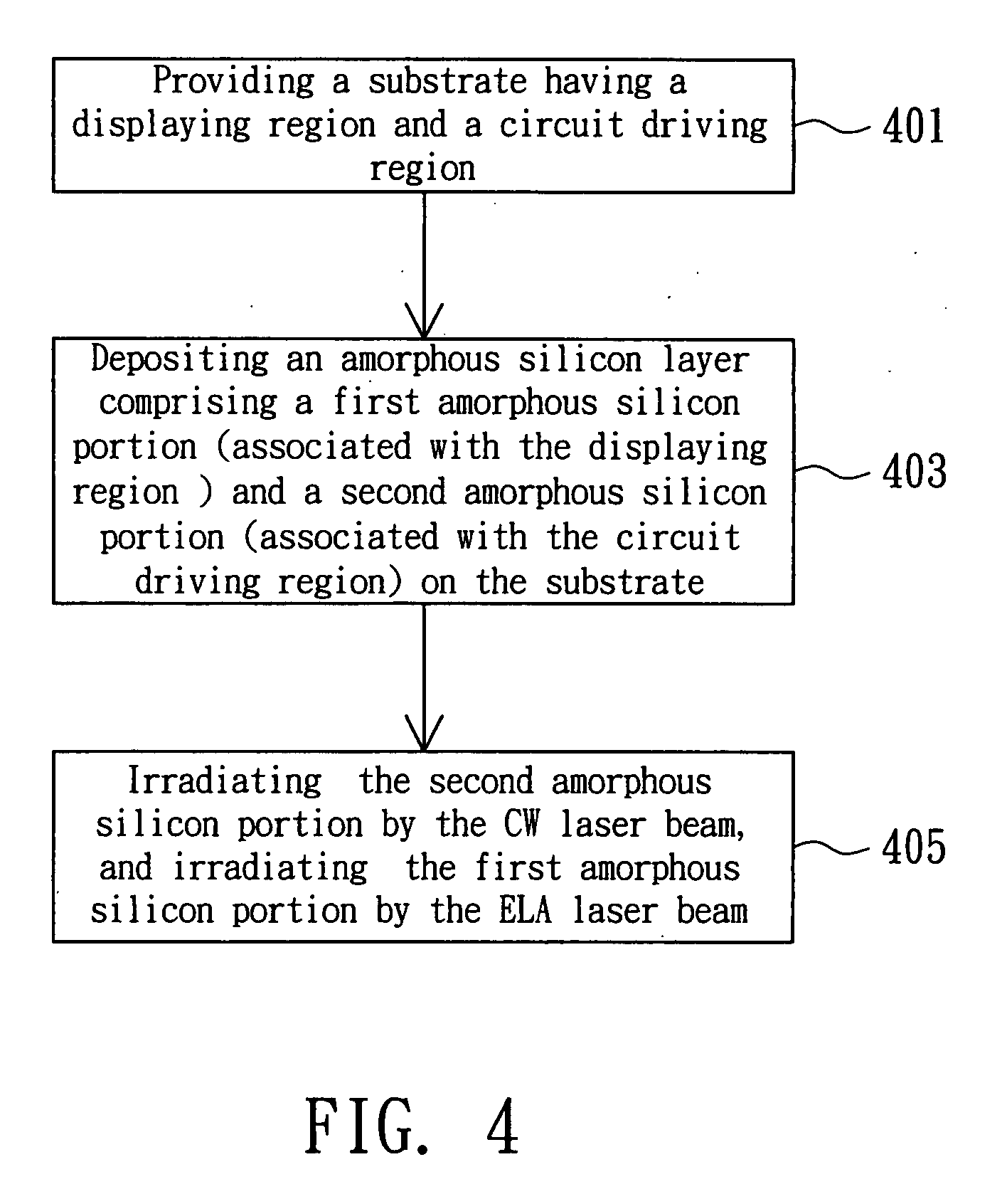
[0022] In the present invention, the displaying region and the circuit driving region of a display panel may be crystallized by using different laser annealing methods, so that the throughput is increased and the mobility of the carriers in the circuit driving region is improved. In the preferred embodiment, the circuit driving region is crystallized by the continuous wave (CW) laser annealing method and the displaying region crystallized by the excimer laser annealing (ELA) method, continuous grain silicon (CGS) method, sequential lateral solidification (SLS) method or metal induced lateral crystallization (MILC) method. Therefore, the polysilicon portion corresponding to the circuit driving region has a larger grain size and more regular grain boundary, resulting in good electrical characteristics, particularly in the mobility of carriers. Although the polysilicon portion corresponding to the displaying region has a smaller grain size, the crystallization process is timesaving, re...


PUM


Abstract

A display panel comprises a substrate having a displaying region (such as active organic light emitting region) and a circuit driving region; and a polysilicon layer formed on the substrate and having a first polysilicon portion and a second polysilicon portion respectively corresponding to the displaying region and circuit driving region, wherein the grain size of the second polysilicon portion crystallized by continuous wave (CW) laser annealing method is larger than that of the first polysilicon portion crystallized by excimer laser annealing (ELA) method.

Description

[0001] This application is a divisional application of pending U.S. application Ser. No. 11 / 258,910 filed Oct. 27, 2005.BACKGROUND OF THE INVENTION [0002] 1. Field of the Invention [0003] The invention relates in general to a display panel and fabricating method thereof, and more particularly to a method for transforming amorphous silicon to poly-silicon by selective laser crystallization and the display panel fabricated by using the same. [0004] 2. Description of the Related Art [0005] According to the circuit driving method, the organic light emitting diode display panel can be divided into two groups. One is a passive matrix organic light emitting diode display panel (PMOLED display panel), and the other group is an active matrix organic light emitting diode display panel (AMOLED display panel). The thin film transistor (TFT) and the storage capacitor are used in the AMOLED to control the gray scale performance of the organic light emitting device (OLED). [0006] Generally, the PM...

Claims


Application Information

Patent Timeline
Patent Type & Authority Applications(United States)
IPC IPC(8): H01L21/84
CPCH01L21/2026H01L27/1285H01L51/56H01L27/3244H01L27/1296H01L21/02686H01L21/02683H01L21/02532H01L21/02691H10K59/12H10K71/00H01L21/02595
Inventor HSU, TSUNG-YICHANG, CHIH-HSIUNG
Owner XIAMEN TIANMA DISPLAY TECH CO LTD
Learn More