Error Correction Coding Apparatus and Error Correction Decoding Apparatus

Active Publication Date: 2008-04-17
MITSUBISHI ELECTRIC CORP
View PDF6 Cites 15 Cited by
  • Summary
  • Abstract
  • Description
  • Claims
  • Application Information

AI Technical Summary

Benefits of technology

[0010] As a result, because the coding processing can be carried out without being restricted b

Problems solved by technology

A problem with the prior art error correction coding apparatus constructed as mentioned above is that because it is necessary to perform coding processing and transmission processin

Method used


Image

  • Error Correction Coding Apparatus and Error Correction Decoding Apparatus
  • Error Correction Coding Apparatus and Error Correction Decoding Apparatus
  • Error Correction Coding Apparatus and Error Correction Decoding Apparatus

Examples


embodiment 1

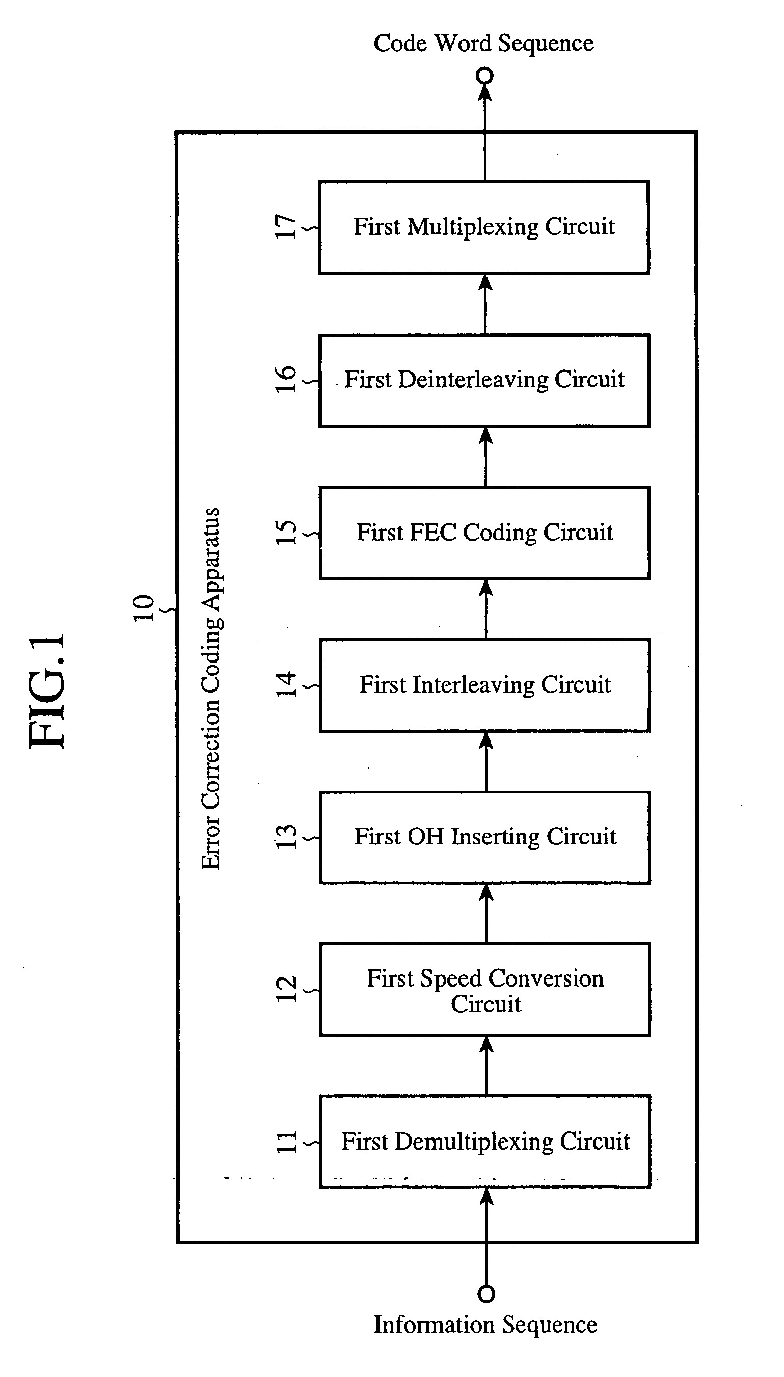
[0024]FIG. 1 is a block diagram showing the structure of an error correction coding apparatus 10 in accordance with embodiment 1 of the present invention. As shown in the figure, the error correction coding apparatus 10 is provided with a first demultiplexing circuit (a frame generating unit) 11, a first speed conversion circuit (the frame generating unit) 12, a first overhead (OH) inserting circuit (the frame generating unit) 13, a first interleaving circuit (a first interleaving unit) 14, a first FEC coding circuit a (first coding unit) 15, a first deinterleaving circuit (a first deinterleaving unit) 16, and a first multiplexing circuit (a multiplexing unit) 17.

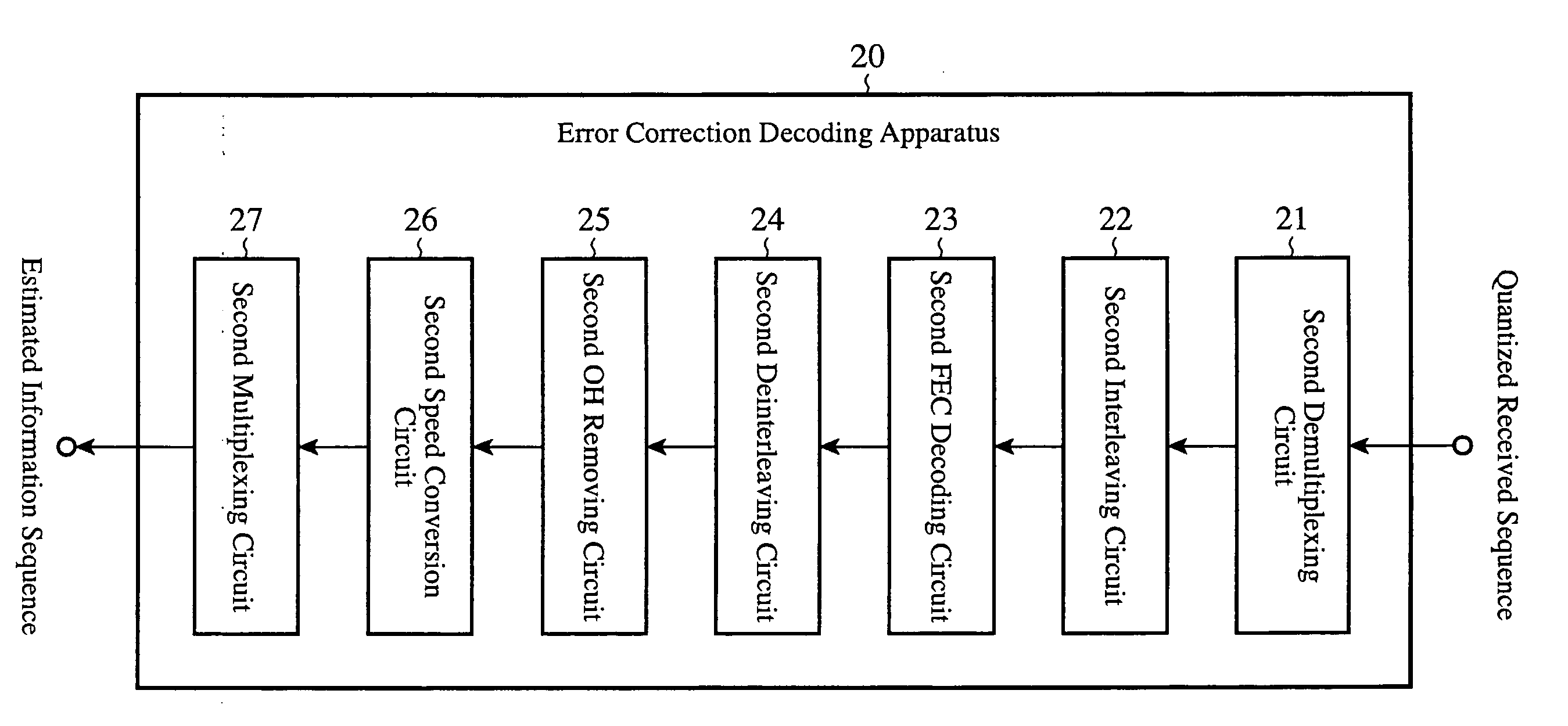
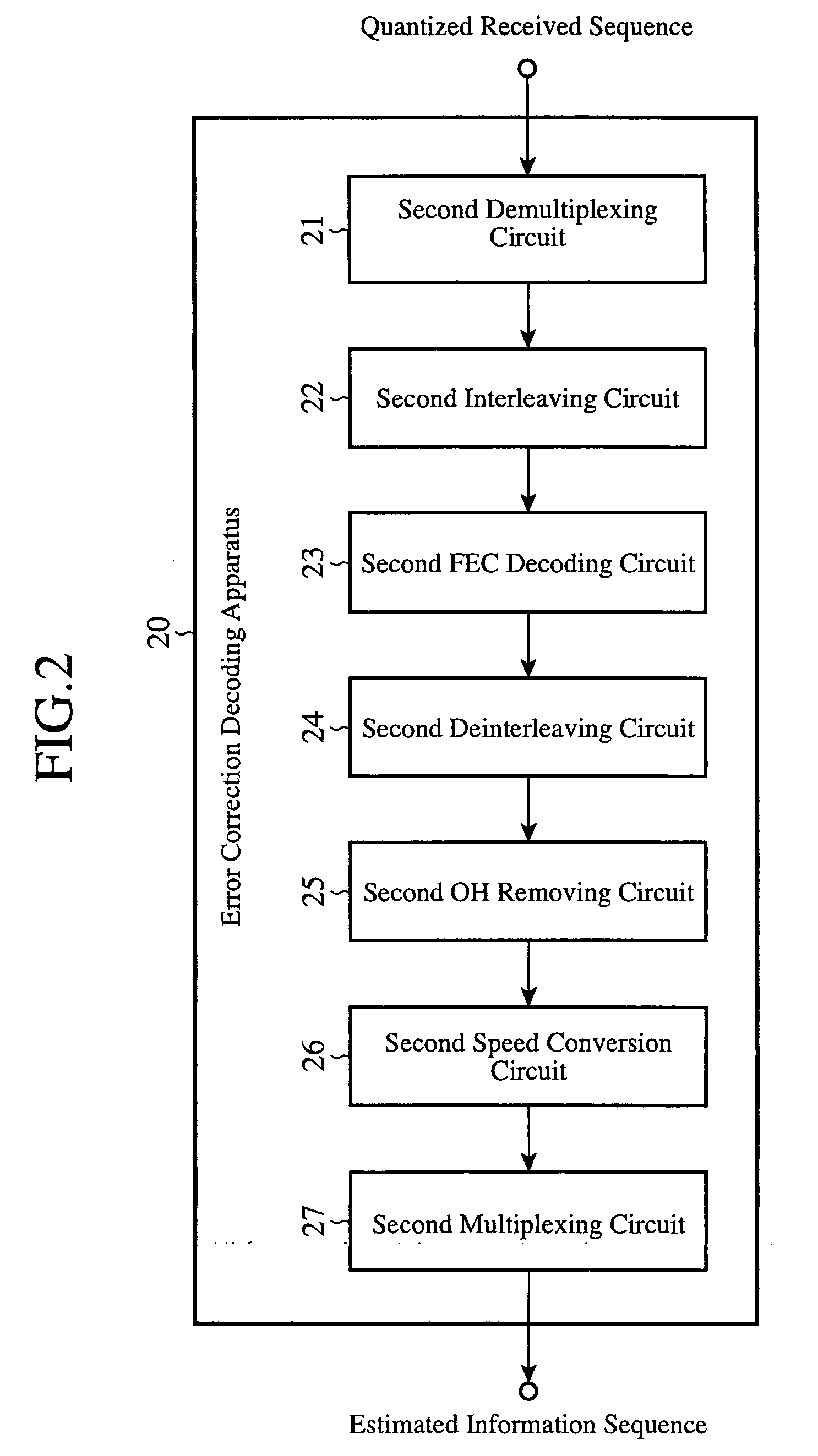
[0025]FIG. 2 is a block diagram showing the structure of an error correction decoding apparatus 20 which corresponds to the error correction coding apparatus 10. As shown in the figure, the error correction decoding apparatus 20 is provided with a second demultiplexing circuit (a demultiplexing unit) 21, a second interleav...

embodiment 2

[0065]FIG. 6 is a block diagram showing the structure of an error correction coding apparatus 40 in accordance with embodiment 2 of the present invention. The same reference numerals as shown in FIG. 1 denote the same components, respectively. As shown in the figure, the error correction coding apparatus 40 is provided with a 1-1th interleaving circuit (a first interleaving unit) 41, a 1-2th interleaving circuit (a third interleaving unit) 42, a second FEC coding circuit (a first coding unit) 43, a 1-2th deinterleaving circuit (a third deinterleaving unit) 44, a 1-1th deinterleaving circuit (a first deinterleaving unit) 45, and a third FEC coding circuit (a second coding unit) 46.

[0066]FIG. 7 is a block diagram showing the structure of an error correction decoding apparatus 50 in accordance with embodiment 2 of the present invention. The same reference numerals as shown in FIG. 2 denote the same components, respectively. As shown in the figure, the error correction decoding apparat...


PUM


Abstract

An error correction coding apparatus includes a frame generating unit for buffering inputted information sequence data in frame buffers which correspond to units to be coded, respectively, a first interleaving unit for rearranging the information sequence data within two or more of the frame buffers, a first coding unit for coding the information sequence data rearranged by the first interleaving unit for each of the frame buffers, and for buffering an error correcting code generated thereby in the frame buffer, a first deinterleaving unit for rearranging code word sequence data in the frame buffer which is coded by the first coding unit according to a procedure which is reverse to that which the first interleaving unit uses, and a multiplexing unit for outputting, as transmission information, the code word sequence data rearranged by the first deinterleaving unit.

Description

FIELD OF THE INVENTION [0001] The present invention relates to an error correction coding apparatus and an error correction decoding apparatus for use in a lightwave transmission system. BACKGROUND OF THE INVENTION [0002] In accordance with an error correction coding method defined by ITU-T recommendation G.975 shown in patent reference 1, a transmit side converts a transmission information sequence inputted thereto in series order into 128 parallel information sequences using an FEC (Forward Error Correction) demultiplexing circuit. It can be considered that this conversion is interleaving processing having a depth of 128. An overhead is added to the 128 parallel information sequences, and a speed conversion corresponding to an FEC parity part is then performed on them. [0003] After that, they are coded in units of 8 parallels high and 239 times width with RS (Reed Solomon) codes. This coding processing is carried out in such a manner that 16 coding processes are done in parallel, ...

Claims


Application Information

Patent Timeline
IPC IPC(8): H03M13/27G06F11/16
CPCH03M13/1515H03M13/2909H03M13/27H03M13/152
Inventor MIYATA, YOSHIKUNIYOSHIDA, HIDEOOUCHI, KAZUHIDESHIMIZU, KATSUHIROKOBAYASHI, TATSUYA
Owner MITSUBISHI ELECTRIC CORP
Why Eureka
Try Eureka