Video data transmission processing method, video data sending processing method, apparatus, network system

a video data and transmission processing technology, applied in the field of video data transmission technologies, can solve the problems of packet loss, data packet loss rate is relatively low, and the quality of decoded video is severely reduced, so as to improve the error tolerance capability of streams

Active Publication Date: 2015-12-15
HUAWEI TECH CO LTD
View PDF20 Cites 3 Cited by
  • Summary
  • Abstract
  • Description
  • Claims
  • Application Information

AI Technical Summary

Benefits of technology

[0006]Embodiments of the present invention provide a video data transmission processing method, a video data sending processing method, an apparatus, and a network system, so as to improve the error tolerance capability of a stream in different network environments with different packet loss rates.
[0024]In the video data transmission processing method, video data sending processing method, apparatus, and network system provided in the embodiments of the present invention, the data server obtains error tolerance aid information corresponding to the to-be-sent stream according to packet loss rates corresponding to at least two transmission networks in the data transmission network system. Therefore, according to different packet loss rates of transmission networks, the data forwarding node can use the error tolerance aid information to quickly generate the error tolerance stream compliant with the packet loss characteristics of the subsequent transmission network, which can improve the error tolerance capability of streams in different network environments with different packet loss rates.

Problems solved by technology

For video stream applications, a delay and packet loss in network transmission may cause that a video packet is unavailable, so that quality of a decoded video decreases severely.
In a wired network, the data packet loss rate is relatively low, and packet loss is mainly caused by congestion of routers in the network.
However, in a wireless network, a high packet loss rate is caused by limited bandwidth, high delay, and high bit error rate.
A video agent is used as a transcoder to decode an original stream and then encode it, which increases complexity of the transcoder, and also increases a system delay.
However, this method generates redundant frames in the case of a given packet loss rate, which may cause a waste of network resources.
However, in order for the user after the second data forwarding node to obtain better video decoding quality, the video server needs to add much redundancy in the stream, thereby causing a waste of bandwidth in the channel from the video server to the first data forwarding node.
If the stream is generated according to a high packet loss rate, the redundancy is excessive, and therefore the utilization rate of bandwidth resources is low; or, if the stream is generated according to a low packet loss rate, the video quality deteriorates when the network conditions become worse.

Method used


Image

  • Video data transmission processing method, video data sending processing method, apparatus, network system
  • Video data transmission processing method, video data sending processing method, apparatus, network system
  • Video data transmission processing method, video data sending processing method, apparatus, network system

Examples


first embodiment

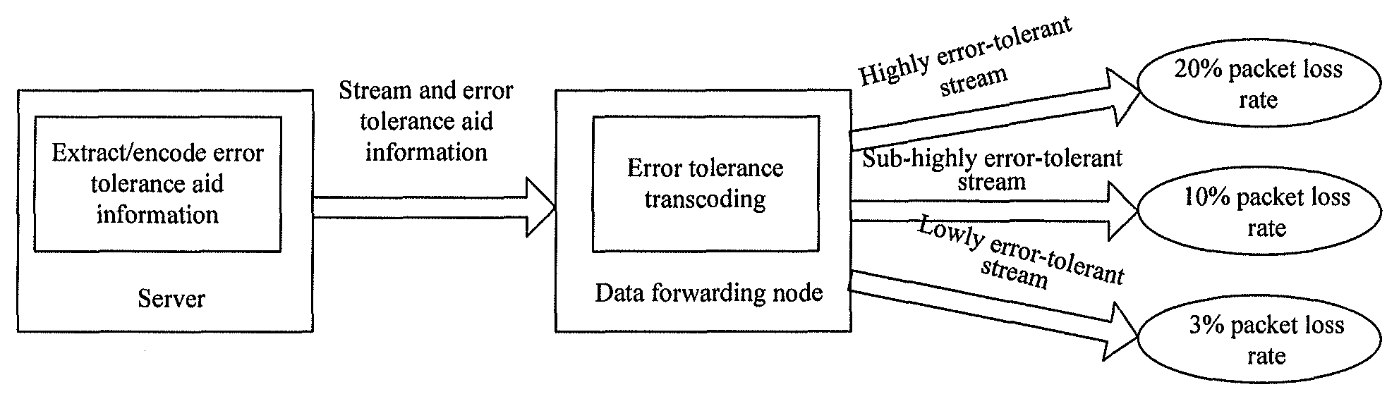
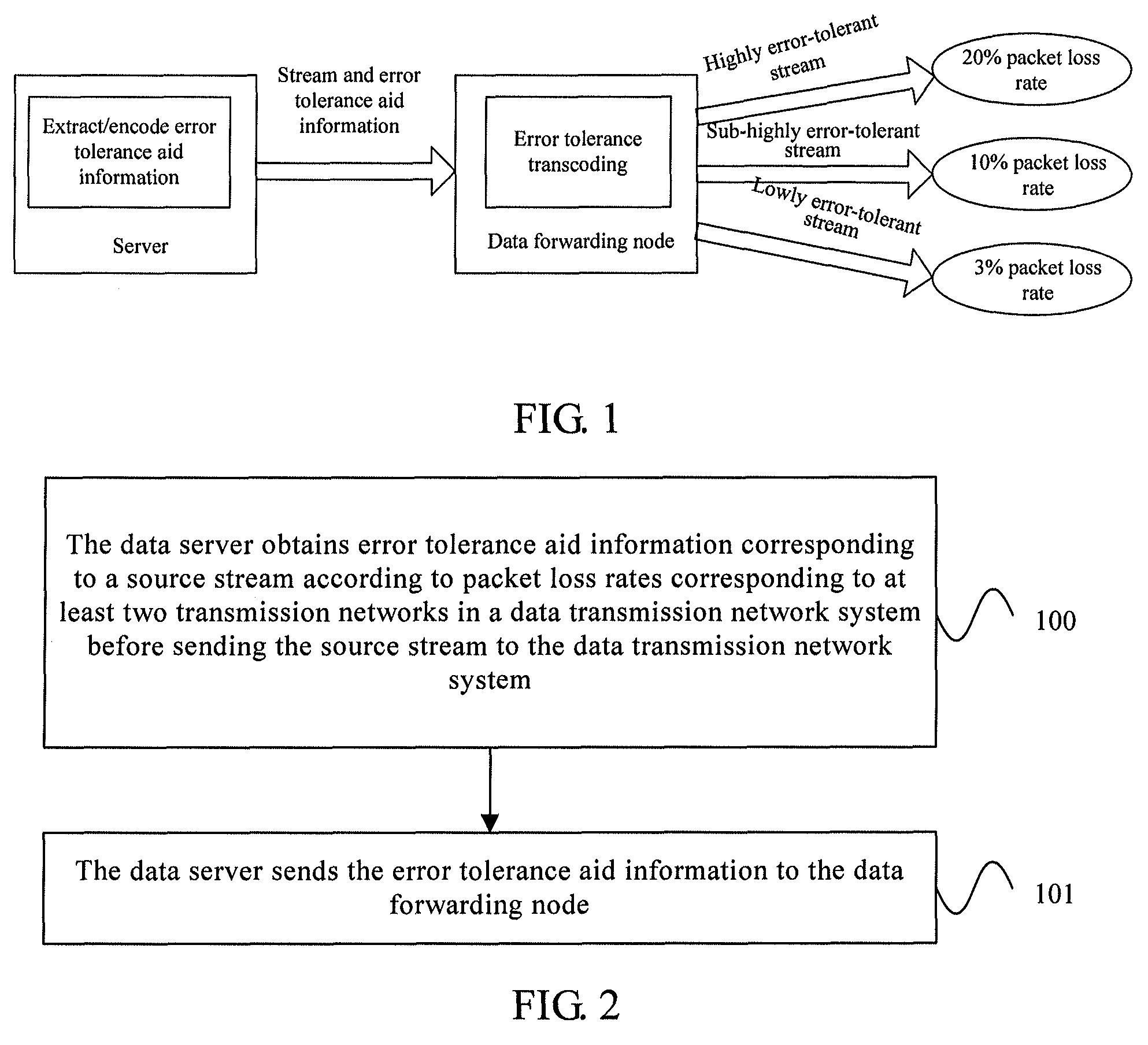
[0112]FIG. 12 is a schematic structure diagram of a network device according to the present invention. As shown in FIG. 12, the network device includes a first obtaining module 21 and a second sending module 22. The first obtaining module 21 is configured to obtain error tolerance aid information corresponding to a source stream according to packet loss rates corresponding to at least two transmission networks in a data transmission network system before sending the source stream to the data transmission network system, where the error tolerance aid information is used by a data forwarding node in the data transmission network system to perform error tolerance coding processing on the received stream to obtain an error tolerance stream for reference; and the second sending module 22 is configured to send the error tolerance aid information to the data forwarding node.

[0113]Specifically, before sending a video stream to a certain data forwarding node in the data transmission network ...

second embodiment

[0115]FIG. 13 is a schematic structure diagram of a network device according to the present invention. As shown in FIG. 13, the network device includes a first obtaining module 21 and a second sending module 22. The first obtaining module 21 includes at least one of submodules in the following, where the submodule includes the following:

[0116]A first obtaining submodule 211 is configured to obtain, according to the packet loss rates corresponding to at least two transmission networks in the data transmission network system, error tolerance aid information for the data forwarding node to adjust redundant frames adaptively for the received stream to obtain an error tolerance stream. The error tolerance aid information includes description information about the redundant frame sets corresponding to the respective packet loss rates of the at least two transmission networks in the data transmission network system respectively. The redundant frame sets are configured to identify data fram...


PUM


Abstract

Embodiments of the present invention provide a video data transmission processing method, a video data sending processing method, an apparatus, and a network system. The data transmission processing method includes: receiving a source stream sent from a source transmission network to a target transmission network; performing, according to respective packet loss rates of the source transmission network and the target transmission network as well as error tolerance aid information corresponding to the source stream, error tolerance coding processing on the source stream to obtain an error tolerance stream; and sending the obtained error tolerance stream to the target transmission network.

Description

CROSS-REFERENCE TO RELATED APPLICATIONS[0001]This application is a continuation of International Application No. PCT / CN2010 / 077526, filed on Sep. 30, 2010, which claims priority to Chinese Patent Application No. 200910179726.5, filed on Sep. 30, 2009, both of which are hereby incorporated by reference in their entireties.FIELD OF THE INVENTION[0002]The present invention relates to the field of video data transmission technologies, and in particular, to a video data transmission processing method, a video data sending processing method, an apparatus, and a network system.BACKGROUND OF THE INVENTION[0003]In an existing video transmission application environment, various networks exist, including wired networks and wireless networks. These networks have different data error probabilities, that is, the reliability of signal transmission is different. For example, in a video transmission network, a video stream provided by a video server is forwarded by a media gateway (Media Gateway), a...

Claims


Application Information

Patent Timeline
Patent Type & Authority Patents(United States)
IPC IPC(8): H03M13/00H04N19/40H04N19/166H04N19/147H04N21/2383H04N19/46H04N21/438H04L1/00H04N19/89
CPCH04N21/4382H04L1/007H04N19/147H04N19/166H04N19/40H04N19/46H04N21/2383
Inventor LIU, MENGGUOI, YILI, HOUQIANGYANG, MINGYUANHU, CHANGQI
Owner HUAWEI TECH CO LTD
Why Eureka
Try Eureka