Method and Apparatus for Measuring Flow Through a Conduit by Measuring the Coriolis Coupling Between Two Vibration Modes

a coriolis coupling and flow measurement technology, applied in the direction of liquid/fluent solid measurement, direct mass flowmeter, instruments, etc., can solve the problems of affecting the flow rate of the condui

Active Publication Date: 2008-04-24
MICRO MOTION INC
View PDF5 Cites 17 Cited by
  • Summary
  • Abstract
  • Description
  • Claims
  • Application Information

AI Technical Summary

Benefits of technology

[0094]a means for applying a force to the conduit that will reduce t...

Problems solved by technology

There is usually a zero-flow delay or offset caused by a number of factors such as non-proportional damping, residual flexibility response, electromagnetic crosstalk, or phase delay in instrument electronics.
Unfortunately, the zero-flow offset can be affected by small changes in the ambient environment (such as temperature) ...

Method used


Image

  • Method and Apparatus for Measuring Flow Through a Conduit by Measuring the Coriolis Coupling Between Two Vibration Modes
  • Method and Apparatus for Measuring Flow Through a Conduit by Measuring the Coriolis Coupling Between Two Vibration Modes
  • Method and Apparatus for Measuring Flow Through a Conduit by Measuring the Coriolis Coupling Between Two Vibration Modes

Examples


Embodiment Construction

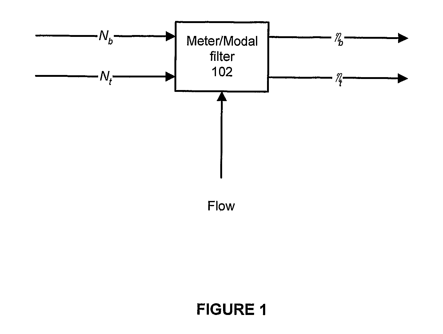
[0105]FIGS. 1-7 and the following description depict specific examples to teach those skilled in the art how to make and use the best mode of the invention. For the purpose of teaching inventive principles, some conventional aspects have been simplified or omitted. Those skilled in the art will appreciate variations from these examples that fall within the scope of the invention. Those skilled in the art will appreciate that the features described below can be combined in various ways to form multiple variations of the invention. As a result, the invention is not limited to the specific examples described below, but only by the claims and their equivalents.

Theoretical Background for a Simple Two Mode Model

[0106]Assuming that the structure of the flow meter is linear and time invariant, it can be described by a set of second order linear differential Equations, (1). In this case x is a vector representing the motion of the structure at various locations on the structure, and FD repre...


PUM


Abstract

A method and apparatus is disclosed that measures the flow through a conduit (702) by measuring the Coriolis coupling between two vibration modes in the conduit. The conduit is first excited at two different vibration modes at two different frequencies (704). The coupling between the two modes is determined by forcing the phases of the two modes at the off mode frequency to be zero (708). The flow through the conduit can then be determined using the magnitude of the forces required to drive the phases of the two modes at the off mode frequency to zero (710).

Description

BACKGROUND OF THE INVENTION[0001]1. Field of the Invention[0002]The invention is related to the field of flow meters, and in particular, to Coriolis flow meters.[0003]2. Description of the Prior Art[0004]Flow rate is measured in a Coriolis flow meter by vibrating a fluid-carrying tube(s) in a sinusoidal motion and measuring the time delay (or phase angle) between the vibration response at two or more locations on the tube(s). For practical situations the time delay varies linearly with flow rate, however, the time delay is generally not zero at zero flow. There is usually a zero-flow delay or offset caused by a number of factors such as non-proportional damping, residual flexibility response, electromagnetic crosstalk, or phase delay in instrument electronics.[0005]This zero-flow offset is typically corrected for by measuring the zero-flow offset at the zero-flow condition and subtracting the measured offset from subsequent measurements made during flow. This would be sufficient to ...

Claims


Application Information

Patent Timeline
IPC IPC(8): G01F1/84
CPCG01F1/849G01F1/8436
Inventor SHELLY, STUART J.SHARP, THOMAS DEAN
Owner MICRO MOTION INC
Why Eureka
Try Eureka