Manifold for a Two-Phase Cooling System

a manifold and liquid cooling technology, applied in the direction of engine diaphragms, diaphragm valves, lighting and heating apparatus, etc., can solve the problems that conventional dry thermal management technology, air convection using fans and heat sinks, is simply not capable of efficiently thermally managing modern electronics, etc., to achieve cost-effective production and efficient installation

Inactive Publication Date: 2008-04-24
TILTON CHARLES L +5
View PDF13 Cites 23 Cited by
  • Summary
  • Abstract
  • Description
  • Claims
  • Application Information

AI Technical Summary

Benefits of technology

[0018] A further object is to provide a manifold for a two-phase cooling system that is cost effective to produce and efficient to install.

Problems solved by technology

Conventional dry thermal management technology (e.g. forced air convection using fans and heat sinks) simply is not capable of efficiently thermally managing modern electronics.

Method used


Image

  • Manifold for a Two-Phase Cooling System
  • Manifold for a Two-Phase Cooling System
  • Manifold for a Two-Phase Cooling System

Examples


Embodiment Construction

A. Overview

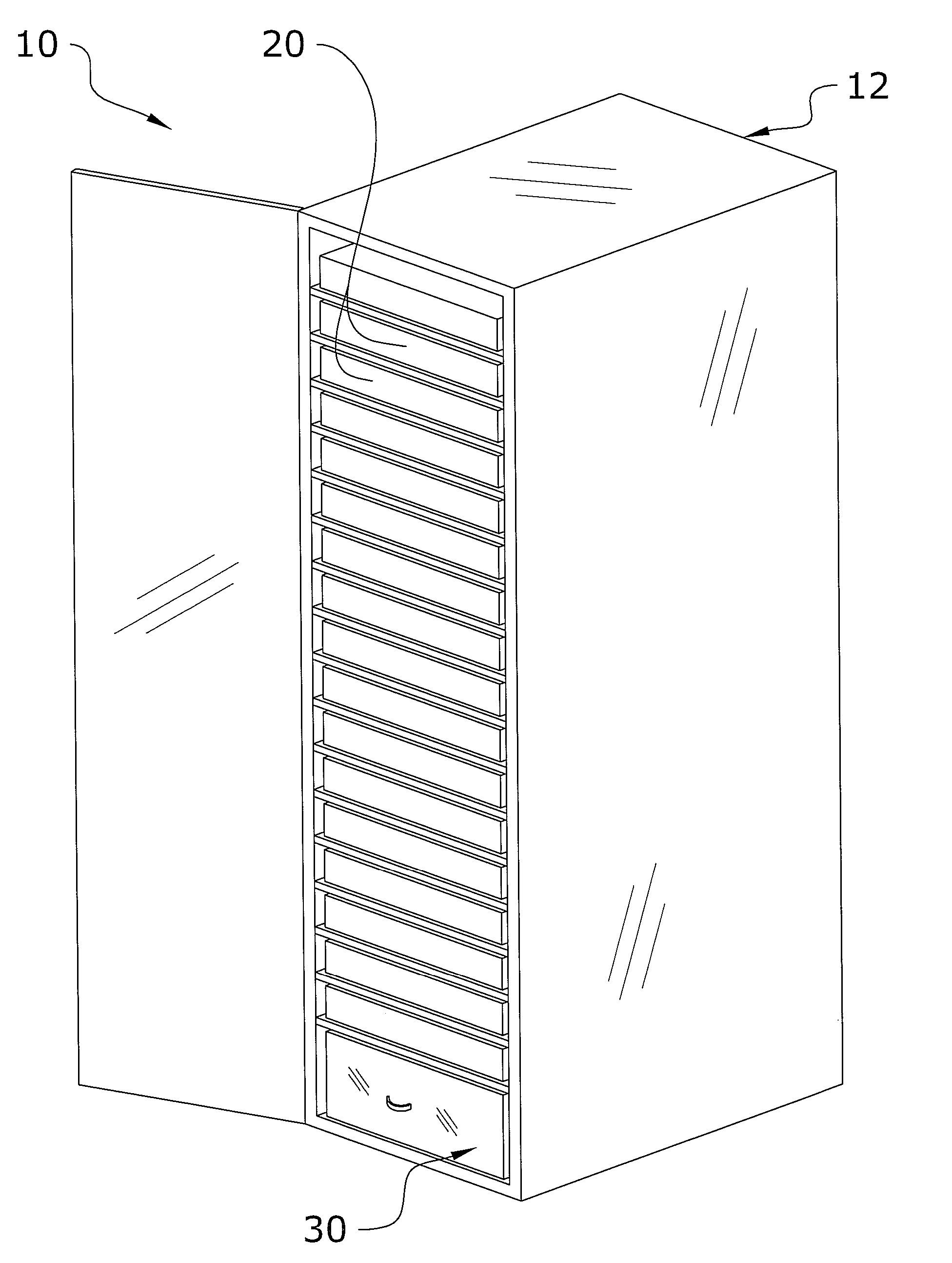
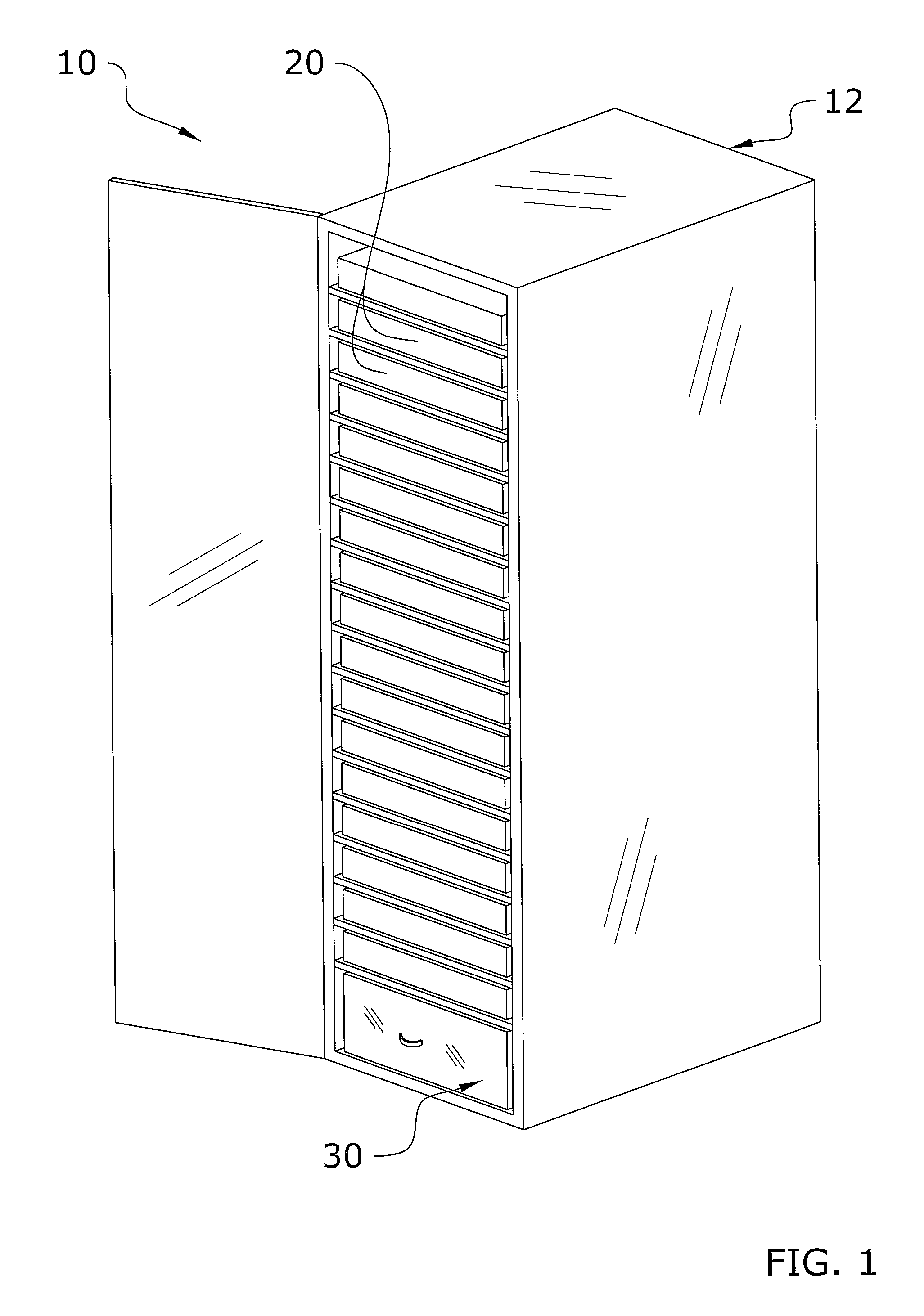
[0033] Turning now descriptively to the drawings, in which similar reference characters denote similar elements throughout the several views, FIGS. 1 through 11 illustrate a manifold for a two-phase cooling system 10, which comprises an extruded manifold having a supply chamber and a return chamber in thermal communication with one another.

B. Rack

[0034] Now referring to FIG. 1, rack system is comprised of a network rack 12 housing one or more servers 20. As is well known in the art of computer electronics and datacenters, the rack 12 provides incremental mounting positions to the servers 20. The servers 20 can be a wide range of sizes ranging from 1 U (1.75″) to greater than 12 U, or blade style. A typical seven foot tall rack 12 can provide 42 rack mounting locations.

C. Thermal Server

[0035] In the preferred embodiment of the present invention, at the bottom of rack system 10 is at least one thermal server 30. As shown in FIG. 1 of the drawings, the thermal server 30 ...


PUM


Abstract

A manifold for a two-phase cooling system for efficiently transferring coolant within a multi-phase cooling system. The manifold for a two-phase cooling system generally includes an extruded manifold having a supply chamber and a return chamber in thermal communication with one another to provide for efficient coolant transfer between a thermal server and a spray module.

Description

CROSS REFERENCE TO RELATED APPLICATIONS [0001] I hereby claim benefit under Title 35, United States Code, Section 119(e) of U.S. provisional patent application Ser. No. 60 / 841,056 filed Aug. 29, 2006 (Docket No. ISR-662). The 60 / 841,056 application is currently pending. The 60 / 841,056 application is hereby incorporated by reference into this application.STATEMENT REGARDING FEDERALLY SPONSORED RESEARCH OR DEVELOPMENT [0002] Not applicable to this application. BACKGROUND OF THE INVENTION [0003] 1. Field of the Invention [0004] The present invention relates generally to fluid distribution manifolds for two-phase liquid cooling systems and more specifically it relates to a manifold for efficiently transferring coolant within a multi-phase cooling system. [0005] 2. Description of the Related Art [0006] Any discussion of the related art throughout the specification should in no way be considered as an admission that such related art is widely known or forms part of common general knowledg...

Claims


Application Information

Patent Timeline
Patent Type & Authority Applications(United States)
IPC IPC(8): F28D15/00
CPCH05K7/20681Y10T137/877
Inventor TILTON, CHARLES L.TILTON, DONALD E.HYDE, TONY E.KNIGHT, PAUL A.DARNTON, BRYAN M.DUNHAM, BRIAN P.
Owner TILTON CHARLES L
Why Eureka
Try Eureka