
Wave Soldering Tank

a soldering tank and wave technology, applied in the direction of non-electric welding apparatus, manufacturing tools, soldering apparatus, etc., can solve the problems of difficult to suppress undulations, poor pump efficiency, and polluted solder discharged from the nozzle, so as to achieve uniform pressure in the solder feed chamber and efficient and uniform pressure application

Active Publication Date: 2008-04-24
SENJU METAL IND CO LTD
View PDF9 Cites 12 Cited by
  • Summary
  • Abstract
  • Description
  • Claims
  • Application Information

AI Technical Summary

Benefits of technology

[0006]The present inventors found that such demands can be met by improving the structure of a soldering tank.
[0008]Thus, one object of the present invention is to provide a wave soldering tank which can supply molten solder to a nozzle with good efficiency, which can eliminate undulations in solder discharged from the nozzle, and which can prevent oxidized coarse dross from being mixed into solder discharged from the nozzle.
[0009]Another object of the present invention is to provide a soldering tank which can more smoothly transport molten solder within a solder feed chamber and which can pressurize the interior of the solder feed chamber without the occurrence of turbulence.
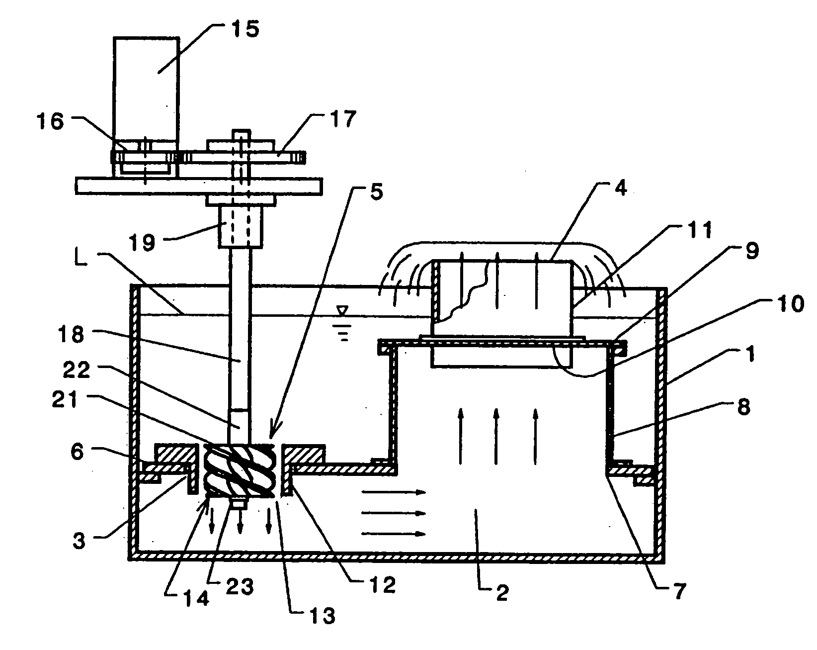
[0012]In a wave soldering tank according to the present invention, the pump is an axial-flow pump, so solder does not flow radially outwards from the pump but is transported in the axial direction of the pump. As a result, pressure is efficiently and uniformly applied to the interior of the solder feed chamber. If the rotation of the pump causes solder to be sent straight downwards, i.e., towards the bottom surface of the tank, when the bottom surface is horizontal, the solder is reflected and rises immediately beneath the pump. However, because the helical blades overlap each other as viewed in the axial direction of the impeller, solder cannot pass in a straight line through the pump, so solder is prevented from rising towards the pump. As a result, the pressure within the solder feed chamber can be uniformly increased without turbulence. “Each of the blades overlaps an adjoining one of the blades when the blades are viewed in the axial direction of the impeller” means that when, for example, the pump impeller has two helical blades spaced from each other around the hub by 180°, each helical blade spirals by at least 180° around the hub between the first and second ends of the blade. When the pump impeller has three helical blades disposed at intervals of 120°, each helical blade spirals around the hub by at least 120° between its first and second ends. This is the same for the case wherein four helical blades are provided. Thus, if the pump impeller includes N blades disposed at intervals of 360 / N degrees around the hub, each blade spirals around the hub by at least 360 / N degrees between its first and second ends.

Problems solved by technology

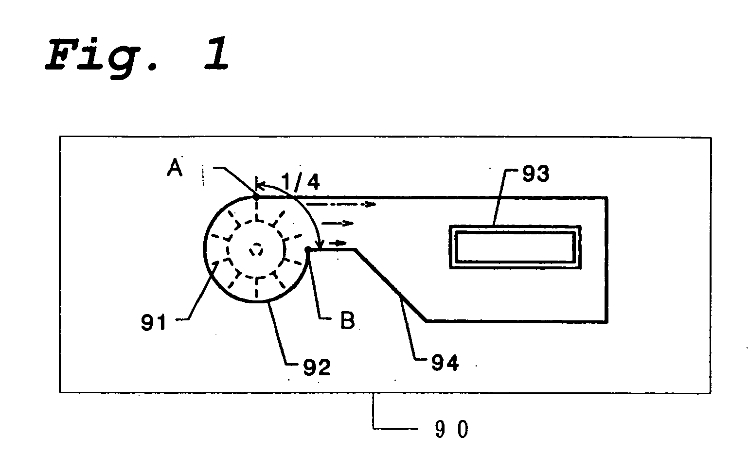
However, with the above-described pump shown in FIG. 1, molten solder is discharged from only approximately ¼ of the entire periphery of the pump, so the efficiency of the pump is poor.
Thus solder which is discharged from the nozzle becomes polluted.
In addition, it is difficult to suppress undulations even with the provision of flow straightening plates.

Method used


Image

  • Wave Soldering Tank
  • Wave Soldering Tank
  • Wave Soldering Tank

Examples


Embodiment Construction

[0020]The structure of a wave soldering tank according to the present invention will be described in greater detail while referring to the accompanying drawings.

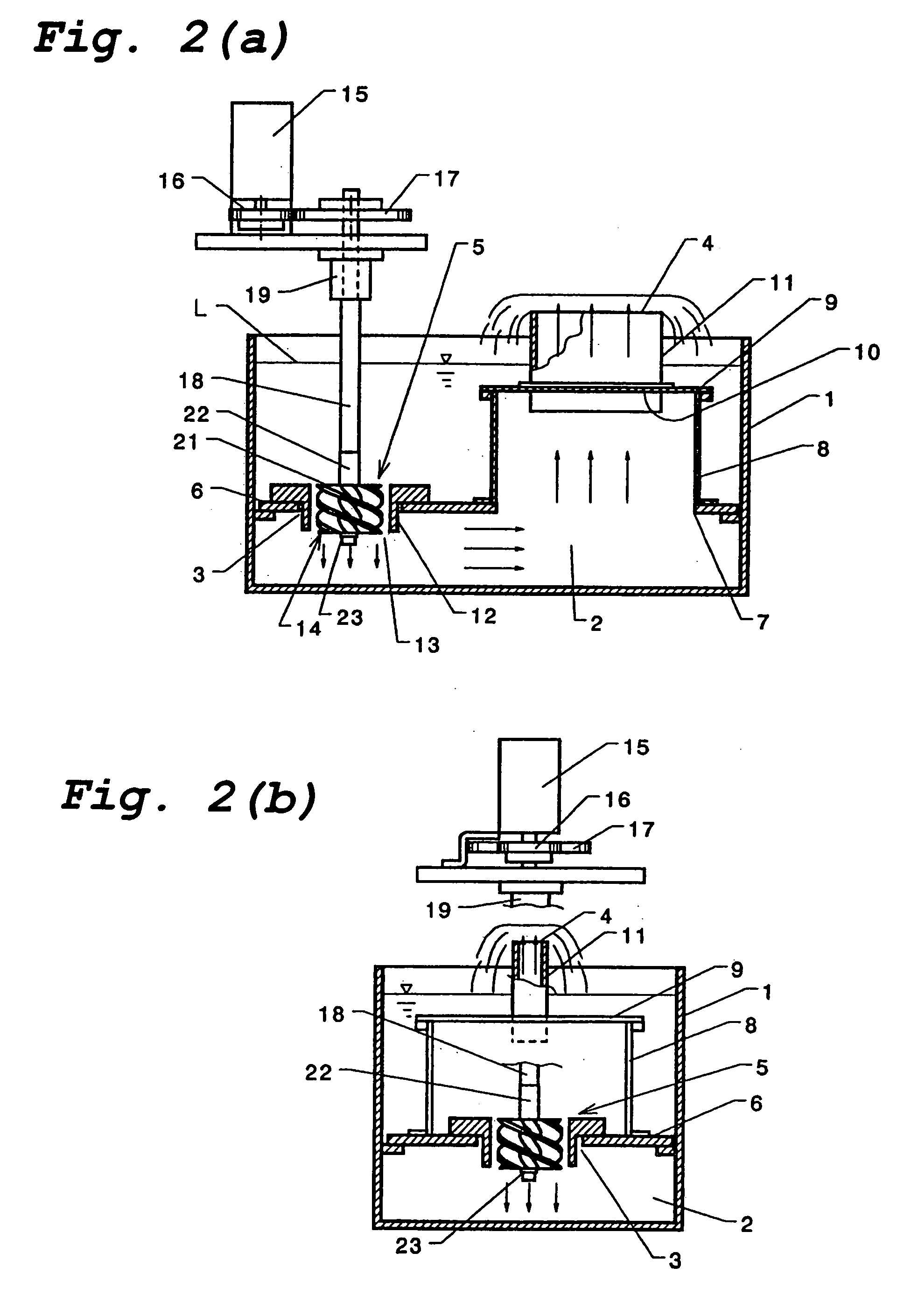
[0021]As shown in FIGS. 2(a) and 2(b), which are cross-sectional elevations of a first embodiment of a wave soldering tank according to the present invention, this embodiment includes a soldering tank body 1 which is open at its upper end and a solder feed chamber 2 disposed in the tank body 1.

[0022]The solder feed chamber 2 has an inlet 3 which is disposed lower than the liquid level L and an outlet 4 which is disposed higher than the liquid level L of molten solder in the tank body 1. A pump 5 is installed at the inlet 3.

[0023]In this embodiment, the solder feed chamber 2 includes a partition 6 which is disposed beneath the liquid level L in the tank body 1 and divides the interior of the tank body 1 into an upper and lower portion. The inlet 3 comprises a through hole formed in the partition 6. Another through hole 7 whic...


PUM

PropertyMeasurementUnit
Lengthaaaaaaaaaa
Lengthaaaaaaaaaa
Angleaaaaaaaaaa

Abstract

A wave soldering tank includes a soldering tank body for housing molten solder and a solder feed chamber disposed within the soldering tank body. An axial-flow, multiple-blade screw-type pump is disposed so as to draw molten solder into the solder feed chamber through an inlet and discharge the molten solder through an outlet. In a preferred embodiment, the pump includes a rotatable hub and a plurality of helical blades secured to the hub at equal intervals in the circumferential direction of the hub, each of the blades overlapping an adjoining one of the blades when the blades are viewed in the axial direction of the impeller.

Description

TECHNICAL FIELD[0001]This invention relates to a wave soldering tank having a pump for supplying molten solder within the tank to a nozzle.BACKGROUND ART[0002]A wave soldering tank typically includes a pump submerged within molten solder in the tank. When the pump is operated, molten solder is sucked into an inlet of the pump and then discharged from a nozzle communicating with an outlet of the pump. By suitably controlling the pump, the solder discharged from the nozzle can be formed into a wave through which electronic parts can be passed for soldering.[0003]FIG. 1 is a schematic plan view of a conventional wave soldering tank disclosed in Japanese Published Unexamined Patent Application 2003-136233. As shown in this figure, a solder feed chamber 94 which is disposed in a soldering tank 90 includes a casing 92 in which a multiple-blade centrifugal pump 91 (such as a sirocco pump) is provided. The solder feed chamber 94 communicates with a nozzle 93 from which molten solder can be ...

Claims


Application Information

Patent Timeline
IPC IPC(8): B23K1/08B23K3/06
CPCB23K3/0653B23K1/08B23K3/08
Inventor TAKAGUCHI, AKIRASATO, ISSAKUHASHIMOTO, NOBORUOKAMURA, JUNICHI
Owner SENJU METAL IND CO LTD
Learn More