Display with a Rotary Driving Device

Inactive Publication Date: 2008-04-24
HIWIN MIKROSYST
View PDF4 Cites 32 Cited by
  • Summary
  • Abstract
  • Description
  • Claims
  • Application Information

AI Technical Summary

Benefits of technology

[0006]The primary objective of the present invention is to provide a display with a rotary driving device, in the structure of this invention, the direct drive motor of the driving device is directly used on the display, so that the user can use wireless control method or manual touch control to rotate the display or the screen. Therefore, the control of the display is quick and easy.
[0007]The secondary objective of the present invention is to provide a display with a rotary driving device, since the display additionally has a function of controlling the angle adjustment of the display or the screen by wireless control or manual touch control, thus improving the product's additional value.
[0008]The primary objective of the present invention is to provide a display with a rotary driving device, in the structure of this invention, the direct drive motor of the driving device is directly used on the display, so that the user can use wireless control method or manual touch control to rotate the display or the screen. Therefore, the control of the display is quick and easy.
[0009]The secondary objective of the present invention is to provide a display with a rotary driving device, since the display additionally has a function of controlling the angle adjustment of the display or the screen by wireless control or manual touch control, thus improving the product's additional value.

Problems solved by technology

However, conventional display still has some disadvantages after a long time use, because the conventional screen or display is immovably fixed to the base, that's called integral type display.
Each angular adjustment of the display must be done by hand, so it is really inconvenient.
However, the micro motor is difficult to control and to stop it precisely at a predetermined position, the motor usually rotates neither excessively nor deficiently.

Method used


Image

  • Display with a Rotary Driving Device
  • Display with a Rotary Driving Device
  • Display with a Rotary Driving Device

Examples


Embodiment Construction

[0020]The present invention will be more clear from the following description when viewed together with the accompanying drawings, which show, for purpose of illustrations only, the preferred embodiment in accordance with the present invention.

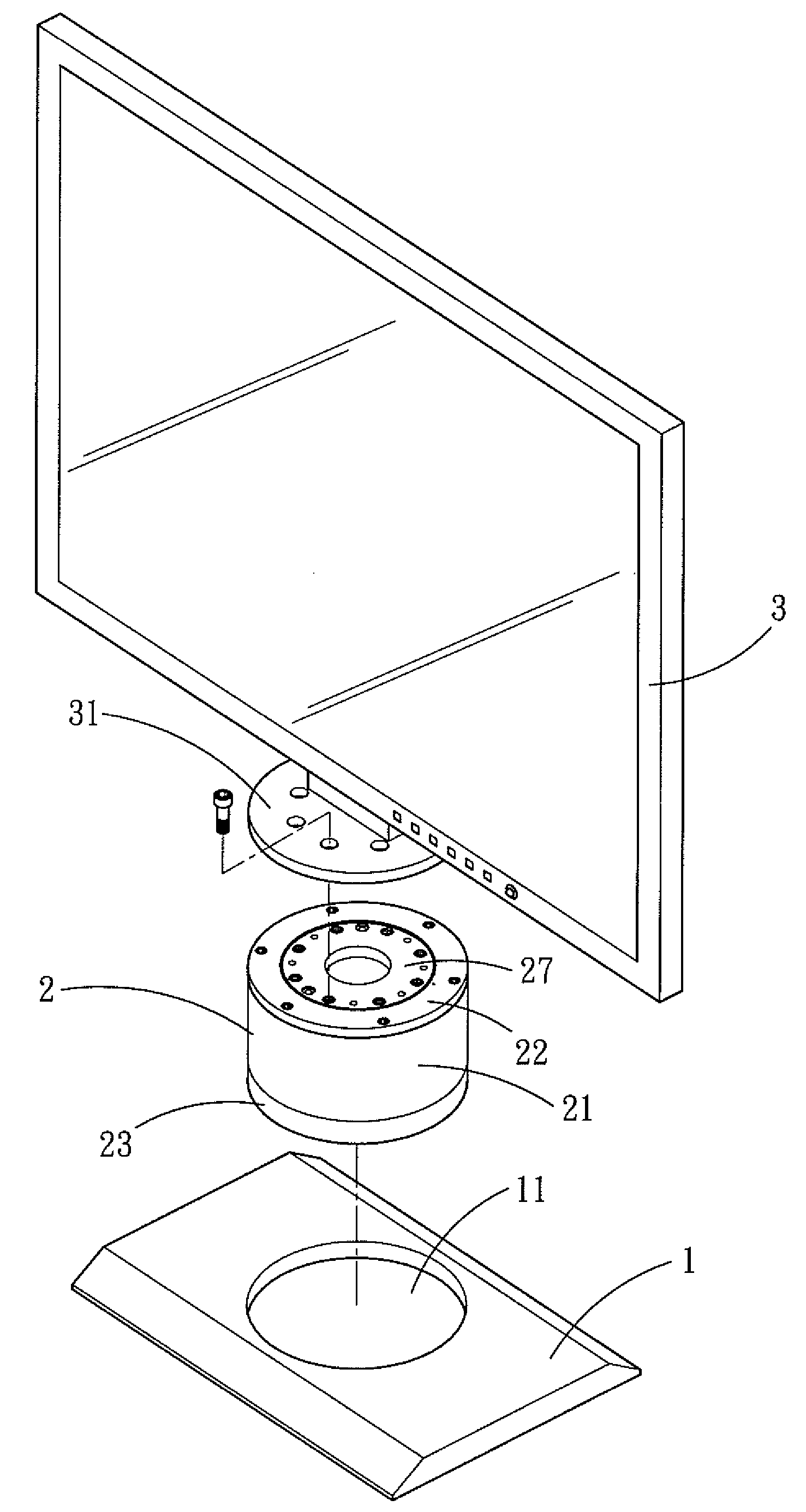
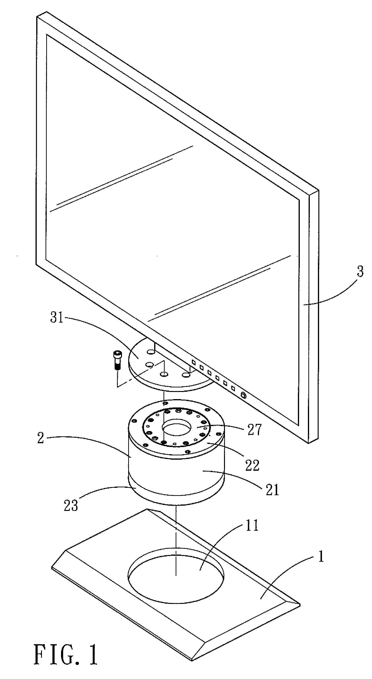
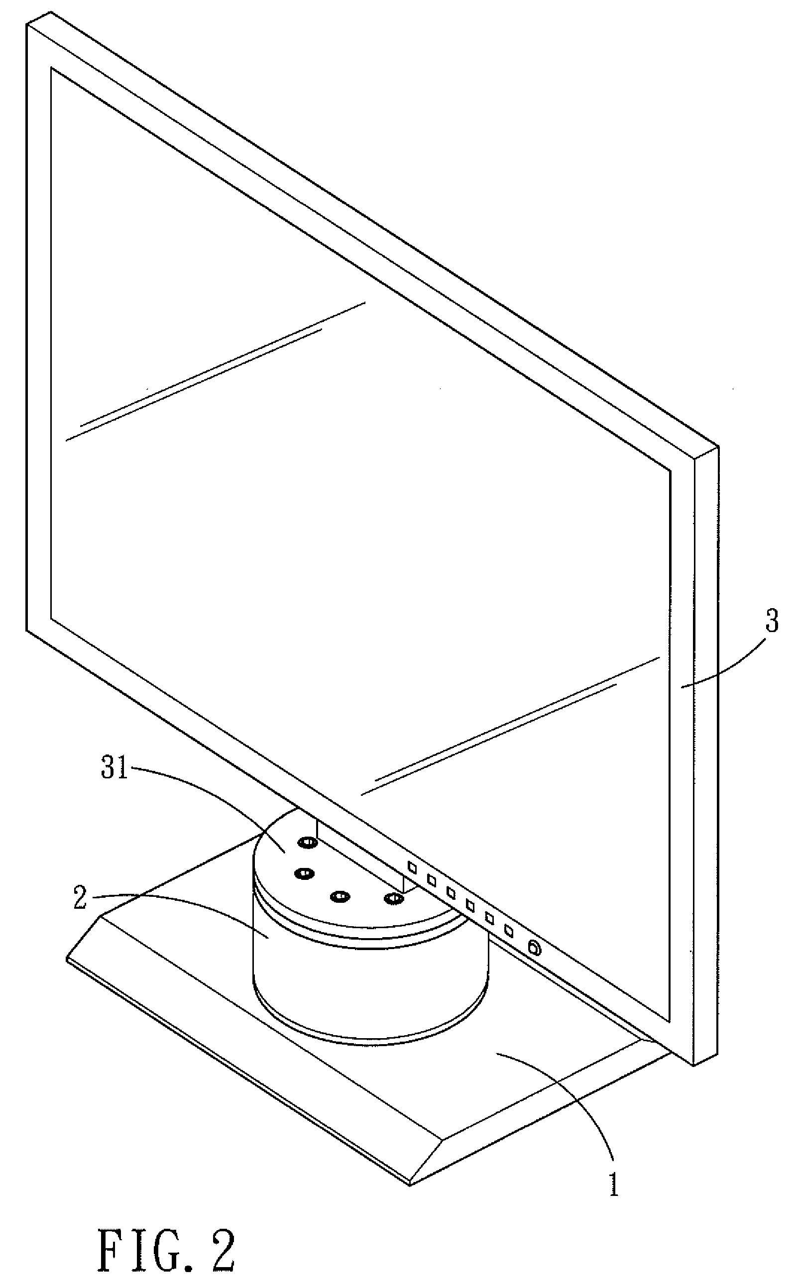
[0021]Referring to FIGS. 1-4, a display with a rotary driving dive in accordance with a preferred embodiment is shown and comprises: a base 1, a driving device 2, and a display 3.

[0022]The base 1 is the same as a base of a conventional base and is provided for positioning the display, in the base 1 of this embodiment is particularly formed a groove 11.

[0023]The driving device 2 is disposed in the groove 11 and includes a direct drive motor (also called torque motor), as shown in FIG. 3. The driving device 2 is provided with a stator 24 and a rotor 25 that are disposed in a spaced defined a housing 21, a cover 22 and a seat 23. The stator 24 is fixed on the seat 23, on the inner periphery of the rotor 25 is disposed a bearing 26, and on the top...


PUM


Abstract

A display with a rotary driving device comprises a base, a driving device, and a display. In assembly, the driving device is mounted on the base, and then the display is fixed on a rotor of the direct drive motor of the driving device. The user can use remote control or manual touch control to set a predetermined angle that he wants the display to rotate, once the display receives signal, it will instantly instruct the direct drive motor of the driving device to rotate the rotor, so that the display will be rotated to a predetermined angle.

Description

BACKGROUND OF THE INVENTION[0001]1. Field of the Invention[0002]The present invention relates to a display, and more particularly to a display with a rotary driving device.[0003]2. Description of the Prior Art[0004]The use of display (such as computer screen, LCD, LCD TV, etc) has been found in various industrial fields, consumers are using various displays every day. Obviously, display brings much convenience to most of the people and is indispensable to people's daily life. However, conventional display still has some disadvantages after a long time use, because the conventional screen or display is immovably fixed to the base, that's called integral type display. If the user wants to angularly adjust the position of the screen or the display, for example, to turn the display or the screen a certain angle to the rear audience or the side audience, he has to rotate it by hand. Each angular adjustment of the display must be done by hand, so it is really inconvenient. Afterwards, to ...

Claims


Application Information

Patent Timeline
IPC IPC(8): H05K5/00H05K7/00
CPCF16M11/08F16M2200/08F16M11/22F16M11/18
Inventor TSAI, CHENG-HANTAI, FANG-FANG
Owner HIWIN MIKROSYST
Why Eureka
Try Eureka