
Locking device

Inactive Publication Date: 2008-04-24
PILZ AUSLANDSBETEILIGUNGEN
View PDF20 Cites 13 Cited by
  • Summary
  • Abstract
  • Description
  • Claims
  • Application Information

AI Technical Summary

Benefits of technology

[0021]Moreover, the first and second components—preferably the first and the second base plates—each advantageously have one of two electronic transmitting / receiving devices that work together in a non-contact manner. The latter can communicate with one another in code. Therefore, by the provision of these devices on or in the two components, an increased handling safety is achieved. Such a transmitting / receiving device can be an RFID based on transponder technology, two communicating infrared transmitting / receiving units, or the like.
[0022]The locking device is configured in a preferred embodiment such that the influence of the magnetic field of the permanent magnet on the electromechanical or electronic element, which reacts to the magnetic field of the permanent magnet, has the effect that the electromagnet is activated. However, it is advantageous to use the interaction between the transmitting / receiving devices to detect the approaching component. It is also possible, however, to configure the influences of the permanent magnet and the transmitting / receiving device differently.

Problems solved by technology

The attenuation of the magnet by the hole that hinders the magnetic flux is disadvantageous in this prior art.
As a result, optimal holding forces are also achieved even if the yoke plate is not optimally oriented relative to the magnet.
It must not be possible for the yoke plate to pivot around a point on the central axis of the yoke plate.

Method used


Image

  • Locking device
  • Locking device
  • Locking device

Examples


Embodiment Construction

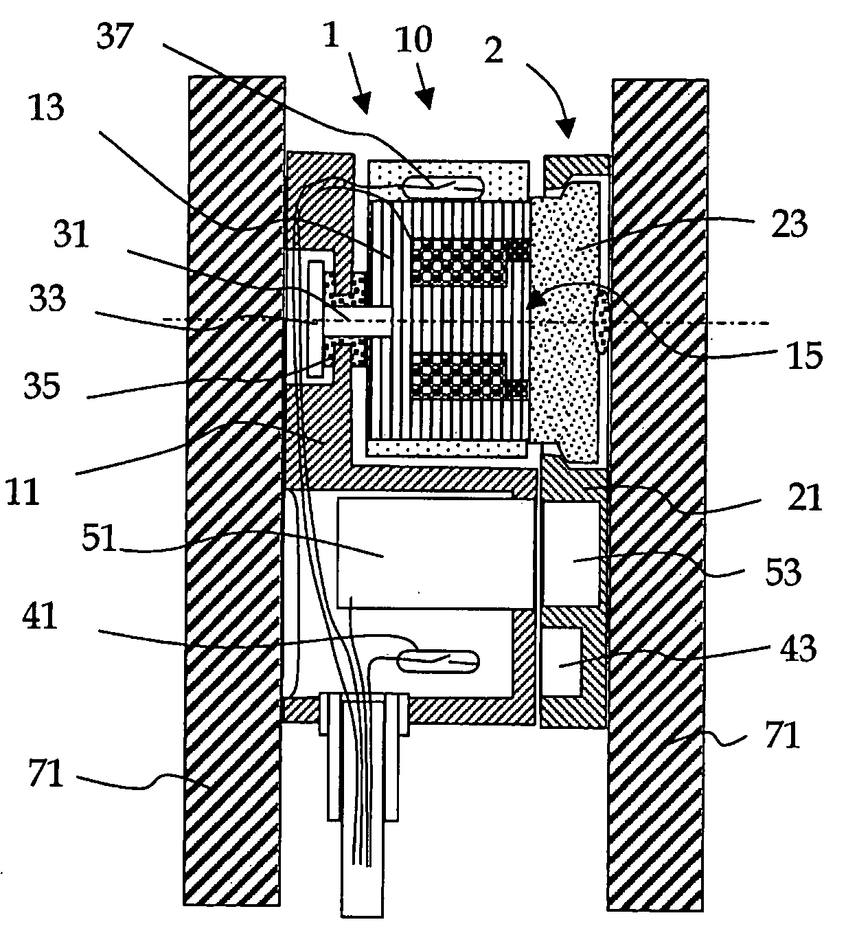
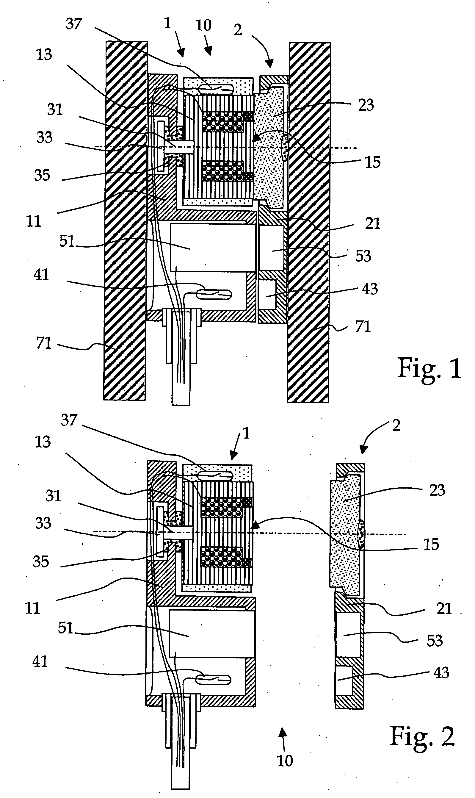
[0032]The exemplary device 10 that is shown mounted on a base 71 in FIG. 1 and detached from the base in FIG. 2 comprises a first component 1 and a second component 2. The first component 1 is essentially formed from a first base plate 11 and an electromagnet 13 that is fastened thereto. The second component 2 is essentially formed from a second base plate 21 and a yoke plate 23 that is fastened thereto. The first and the second components 1, 2 are tightly and immovably mounted on the base 71. The first component 1 is fastened to a solid base 71, in which a closable opening is present. The second component 2 is fastened to a closing part to close this opening. When opening the opening, the bases 71 of the two components are removed from one another and thus lift the components from one another. In FIG. 2, the components 1, 2 are shown in positions that are removed from one another.

[0033]The electromagnet 13 is fastened tightly but movably to the first base plate 11. The mobility is ...


PUM


Abstract

The disclosure relates to a locking system with an electromagnet and a yoke plate that closes the magnetic circuit of the electromagnet. In the latter, the electromagnet is fastened with a fastening element to pivot around a point on a central axis and is tightly fastened in the longitudinal direction of the central axis. Said central axis runs perpendicular to the contact plane between the electromagnet and the yoke plate and through the center of the holding force of the closed electromagnet. As a result, a force that acts against the magnetic force to detach the yoke plate from the pole surface always acts coaxially with the magnetic force, thus keeping the yoke plate from being detached from the pole surface on one side.

Description

RELATED APPLICATIONS[0001]This application claims priority under 35 U.S.C. §119 to Swiss Patent Application No. 01677 / 06 filed in Switzerland on Oct. 23, 2006, the entire contents of which are hereby incorporated by reference in their entireties.TECHNICAL FIELD[0002]A magnetic safety locking device is disclosed with an electromagnet and a yoke plate that works together with the electromagnet.BACKGROUND INFORMATION[0003]A screw-on magnetic door fastener, in which a cylindrical permanent magnet with two pole flanges that are curved in the shape of a barrel is housed in a first component, is known from the German Utility Model No. 231837. The pole flanges interact with a round, movable holding plate. To allow the exact adjustment of the holding plate on the two pole flanges of the permanent magnet, the hole in the holding plate is kept somewhat larger than the diameter of the shank of the fastening screw and is provided with a corresponding countersink. When the holding plate is screwe...

Claims


Application Information

Patent Timeline
IPC IPC(8): H01F7/08
CPCH01H27/002E05C19/166
Inventor SCHMID, MAX
Owner PILZ AUSLANDSBETEILIGUNGEN
Features
  • Generate Ideas
  • Intellectual Property
  • Life Sciences
  • Materials
  • Tech Scout
  • Unparalleled Data Quality
  • Higher Quality Content
  • 60% Fewer Hallucinations
Learn More