Compensation for fluctuations over time in the radiation characteristics of the X-ray source in an XRF analyser

a radiation characteristic and analyzer technology, applied in the field of xray fluorescence analyzers, can solve the problems of adding unknown factors to the intensity fluctuations of the x-ray tube, xrf measurements, and not taking into account any spatial fluctuations of the x-ray beam

Inactive Publication Date: 2008-04-24
HITACHI HIGH TECH ANALYTICAL SCI FINLAND OY
View PDF20 Cites 13 Cited by
  • Summary
  • Abstract
  • Description
  • Claims
  • Application Information

AI Technical Summary

Benefits of technology

[0021]However, the amount of marker material does not need to be very large if the marker material does not need to mechanically support itself. If some other material that is essentially transparent to X-rays is used as the mechanical support, ...

Problems solved by technology

Additionally the electric circuit elements, however meticulously designed and controlled, that feed the input voltage and current to the X-ray tube, are inherently imperfect, which adds an unknown factor to the intensity fluctuations of the X-ray tube.
This is a disadvantage concerning such XRF measurements that otherwise could be performed in a shorter time.
The solutions of FIGS. 1 and 2 share the inherent disadvantage that although they partly help to combat the overall intensity fluctuations over time, they do not take into account any spat...

Method used


Image

  • Compensation for fluctuations over time in the radiation characteristics of the X-ray source in an XRF analyser
  • Compensation for fluctuations over time in the radiation characteristics of the X-ray source in an XRF analyser
  • Compensation for fluctuations over time in the radiation characteristics of the X-ray source in an XRF analyser

Examples


Embodiment Construction

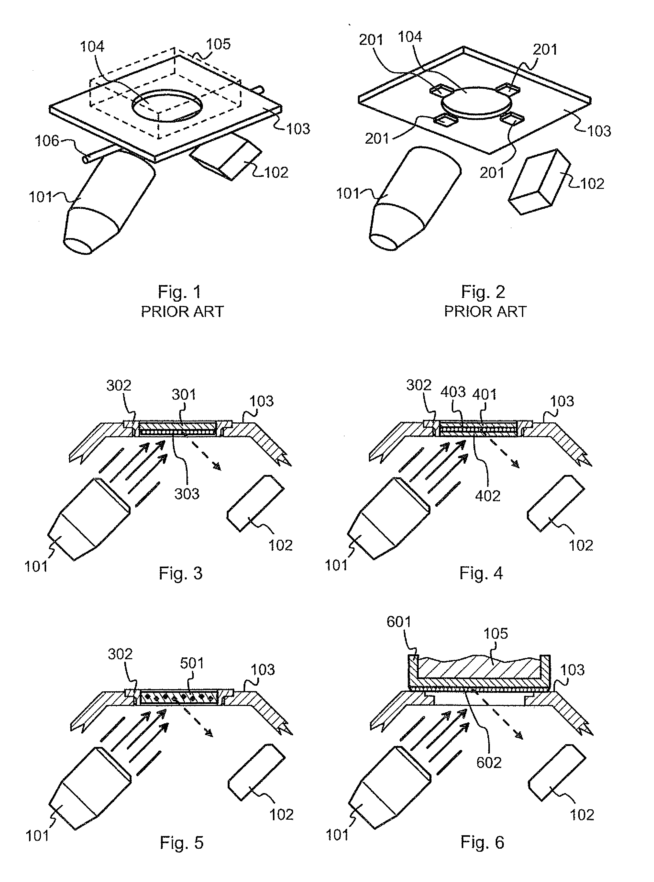
[0035]FIG. 3 illustrates schematically a front end of an XRF analyzer device. The term “front end” is conventionally used to designate that part of the analyzer device that incorporates the X-ray source 101 and the detector 102, and that comprises a part of the outer cover known as the front plate 103 that is configured to come against a sample for performing the XRF measurement. The front plate 103 defines a sample window for the incident X-rays and the fluorescent X-rays to pass through.

[0036]In the embodiment of FIG. 3 a protective window foil 301 is attached to the edges of the sample window with the help of a frame 302. The bulk of the window foil 301 is made of a material that is essentially transparent to X-rays, like diamond, beryllium or a plastic like polyimide. The role of the window foil 301 is basically to protect the inside of the analyzer device from contamination. If a particular gas atmosphere, lowered pressure, or other kind of controlled conditions are maintained ...


PUM


Abstract

An X-ray source (101) is configured to controllably irradiate a sample (105) with incident X-rays through a sample window (104) that has a two-dimensional area. A detector (102) is configured to detect fluorescent radiation coming from the irradiated sample. A carrier (301, 401, 402, 501, 601) is essentially transparent to X-rays and disposed to spatially coincide with a substantial part of the two-dimensional area of the sample window (104). Marker material (303, 403, 602), which is responsive to X-rays by emitting fluorescent radiation, is mechanically supported by said carrier and essentially evenly distributed across at least that part of the carrier that spatially coincides with said two-dimensional area of the sample window.

Description

TECHNICAL FIELD[0001]This invention concerns generally the technology of X-ray fluorescence (XRF) analyzers. Especially the invention concerns a method and an arrangement for making the analysis results less dependent on fluctuations in the radiation characteristics of the X-ray source.BACKGROUND OF THE INVENTION[0002]X-ray fluorescence analysis is a well-known method for investigating the material composition of a sample. X-rays from an X-ray source are allowed to irradiate the sample, which causes atoms of the sample constituents emit fluorescent radiation at characteristic energies. A detector receives the fluorescent radiation. By following the output of the detector it is possible to derive the spectral intensity of the fluorescent radiation. The relative numbers of received fluorescent photons at different energies reveal the proportions of different elements present in the sample.[0003]In some X-ray fluorescence measurements it is important to know the absolute intensity of t...

Claims


Application Information

Patent Timeline
IPC IPC(8): G01N23/223
CPCG01N2223/076G01N23/223
Inventor PUUSAARI, ERKKI TAPANISHIROKOBROD, OLEG
Owner HITACHI HIGH TECH ANALYTICAL SCI FINLAND OY
Why Eureka
Try Eureka