Method Of Detecting Platelet Thrombosis Or Organ Failure
a technology of platelet thrombosis and organ failure, applied in the field of method of detecting platelet thrombosis or organ failure, can solve the problems of organ dysfunction or bleeding tendency, variety of organs falling into dysfunction, and bleeding tendency
- Summary
- Abstract
- Description
- Claims
- Application Information
AI Technical Summary
Benefits of technology
Problems solved by technology
Method used
Image

Examples
example 1
Degradation of Recombinant VWF-Cleaving Protease Antigen by Elastase
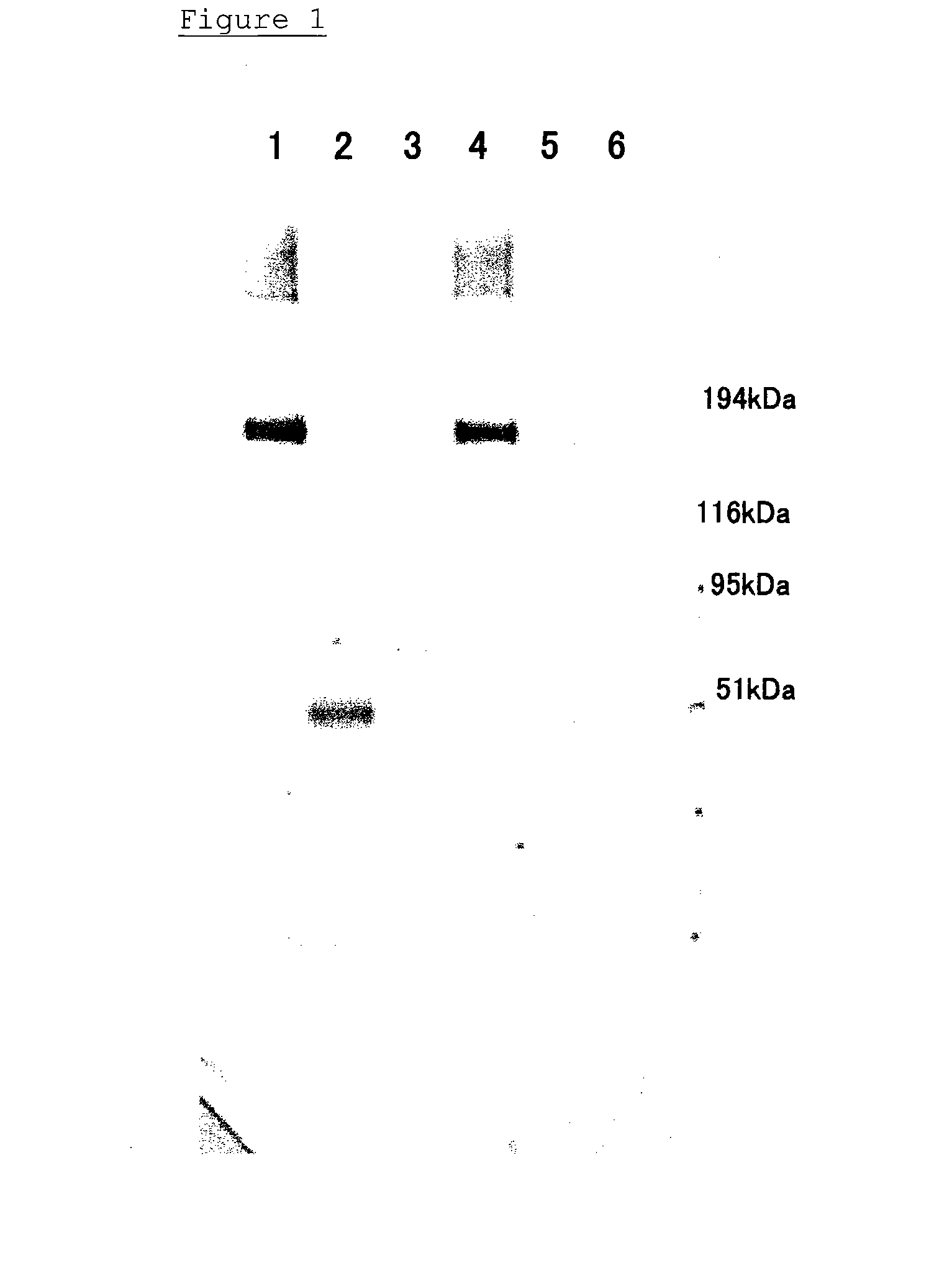
[0046] After 1.5 μg of a recombinant VWF-cleaving protease was dissolved in a Tris buffer / physiological saline solution, elastase was added to the solution to reach a final concentration of 20 nmol / L or 140 nmol / L. Each mixture was incubated at 37° C., and aliquots corresponding to 0.5 μg of the VWF-cleaving protease were collected therefrom after 15 minutes and 1 hour from the beginning of the incubation. The collected samples were subjected to an SDS electrophoresis (5-20% gel) under the non-reduced conditions, and transferred to a PVDF (polyvinylidene difluoride) membrane by Western blotting. The membrane was blocked with a commercially available blocking agent (Block Ace; Dainippon pharmaceutical) at room temperature for 30 minutes, and washed with a Tris buffer. The membrane was incubated in a 1 μg / mL anti-VWF-cleaving-protease monoclonal antibody (WH2-22-1A: epitope=a disintegrin region of VWF-cleaving protea...
example 2
Degradation of Recombinant VWF-Cleaving Protease Antigen by Plasmin or Thrombin
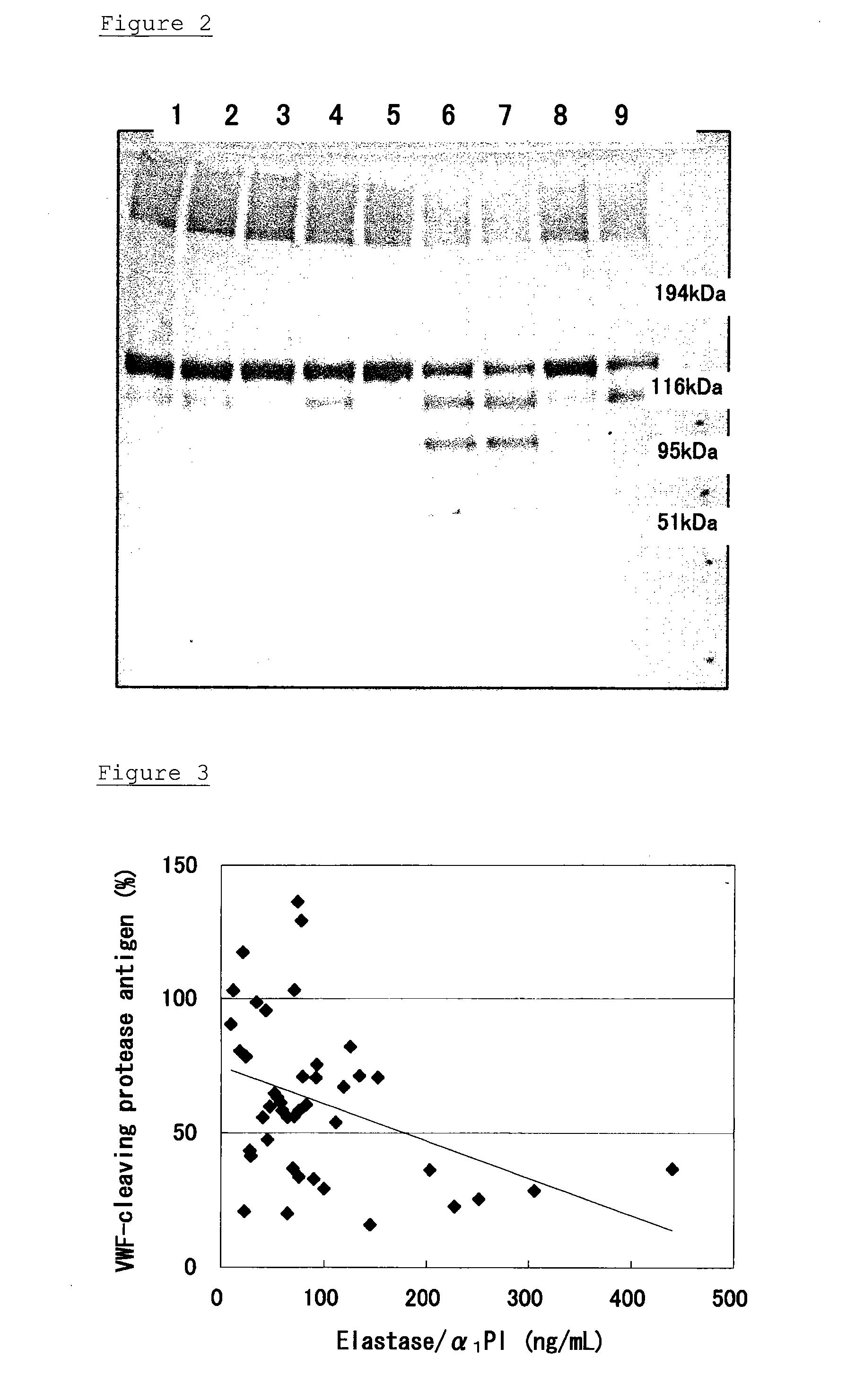
[0055] After 1.5 μg of a recombinant VWF-cleaving protease was dissolved in a Tris buffer / physiological saline solution, a combination of plasminogen (final concentration=1 μmol / L) and tissue plasminogen activator (final concentration=0.2 nmol / L or 2 nmol / L), or thrombin (final concentration=20 mU or 200 mU) was added to the solution. Each mixture was incubated at 37° C., and aliquots corresponding to 0.5 μg of the VWF-cleaving protease were collected therefrom after 15 minutes and 1 hour from the beginning of the incubation. The collected samples were subjected to an SDS electrophoresis, and the Western blotting was carried out, as described in Example 1, to detect the bands of the VWF-cleaving protease. The result is shown in FIG. 2.
[0056] Reaction conditions in each lane shown in FIG. 2 are as follows:
[0057] Lane 1: Reaction at 37° C. for 15 minutes with 0.2 nmol / L tissue plasminogen activator (tPA)...
example 3
Correlation of VWF-Protease with Elastase
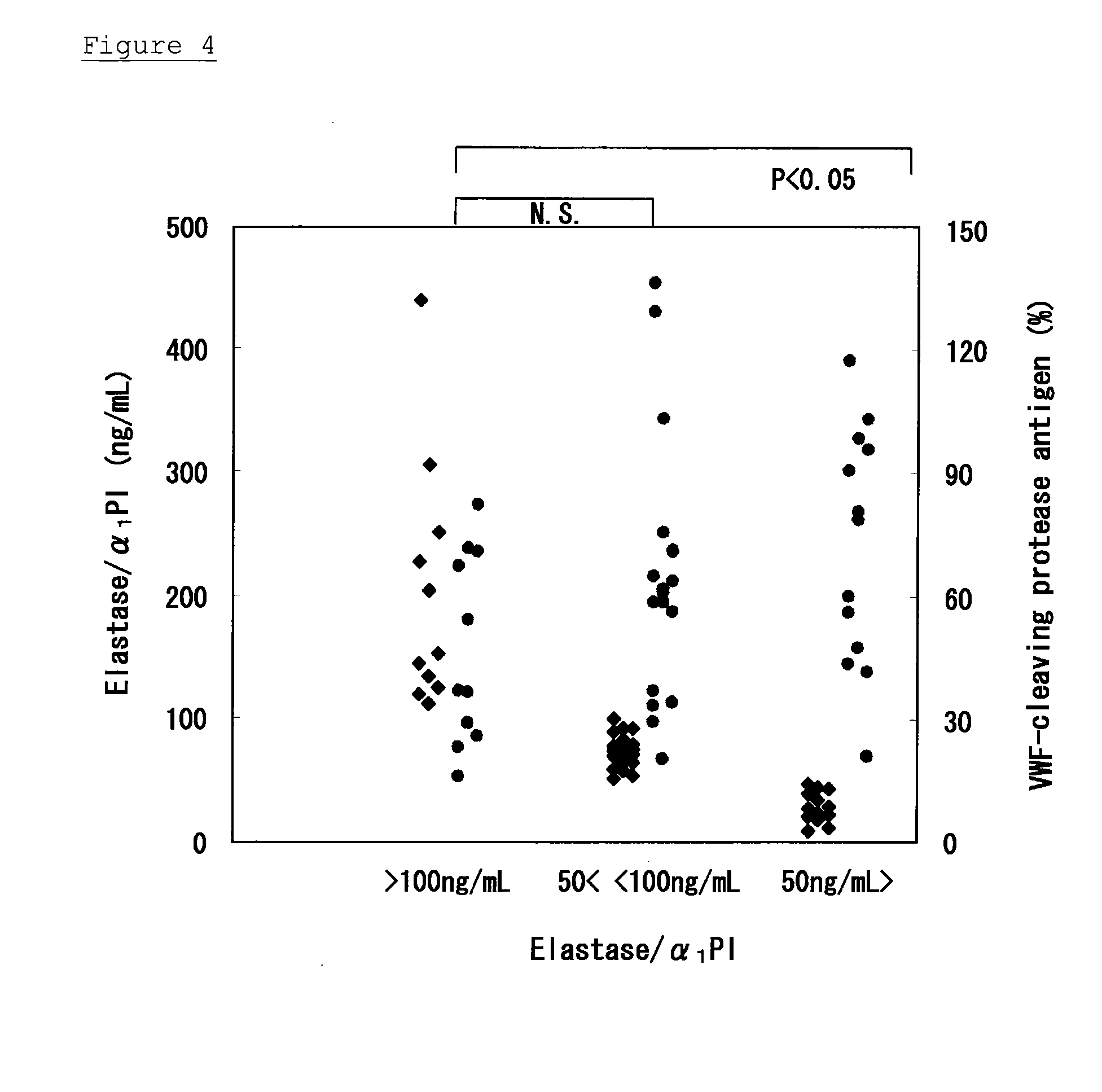
[0067] In this Example, plasma samples collected from healthy people, patients with DIC, and patients with SIRS were used to measure the amounts of the VWF-cleaving protease antigen and elastase contained therein. An amount of the VWF-cleaving protease antigen was measured using a commercially available kit (VWF-cleaving protease ELISA kit; Mitsubishi Kagaku Tatron). An amount of elastase was determined by measuring an amount of elastase / α1-antitrypsin using a commercially available kit (PMN Elastase / α1-PI Complex ELISA Kit; CALBIOCHEM).
[0068] The result is shown in FIGS. 3 and 4. In FIG. 3, the X axis indicates amounts of elastase / α1-antitrypsin (unit=ng / mL), and the Y axis indicates amounts of the VWF-cleaving protease antigen (unit=%). In FIG. 4, the abbreviation N.S. means that no significant difference existed therebetween.
[0069] There was a negative correlation between the amount of elastase / α1-antitrypsin and the amount of the VWF-c...
PUM
 Abstract
Description
Claims
Application Information
 - R&D
- Intellectual Property
- Life Sciences
- Materials
- Tech Scout
- Unparalleled Data Quality
- Higher Quality Content
- 60% Fewer Hallucinations
Browse by: Latest US Patents, China's latest patents, Technical Efficacy Thesaurus, Application Domain, Technology Topic, Popular Technical Reports.
© 2025 PatSnap. All rights reserved.Legal|Privacy policy|Modern Slavery Act Transparency Statement|Sitemap|About US| Contact US: help@patsnap.com