Method and apparatus for controlling the injection rate of a drug solution in a cartridge type motor-driven dental injection syringe

a technology of injection syringe and injection rate, which is applied in the field of cartridge-type motor-driven injection syringe, can solve the problems that dentists cannot arbitrarily adjust the injection operation, and achieve the effect of low injection ra

Inactive Publication Date: 2008-04-24
SHOWA YAKUHIN KAKO
View PDF7 Cites 42 Cited by
  • Summary
  • Abstract
  • Description
  • Claims
  • Application Information

AI Technical Summary

Benefits of technology

[0010] Another object of the present invention is to provide a method and apparatus for controlling the injection rate of an anaesthetic solution in a cartridge type motor-driven injection syringe for dental use wherein that the “low” injection rate for the initial injection can also be maintained for the whole period of injection.
[0011] To attain these objects, the present invention provides a method for controlling the injection rate of an anaesthetic solution in a cartridge type motor-driven injection syringe for dental use, the motor-driven injection syringe being so designed that the electric motor is operatively connected through a reduction gear to a rack and pinion to slowly move a plunger rod and hence a plunger rubber in the cartridge, thereby ejecting the anaesthetic solution through an injection needle, characterized in that the electric motor is adapted to be switched stepwise in speed of revolution between the Low, Medium and High Speed, the starter switch is a two-step operable switch including the first depression for starting the electric motor at the Low Speed and hence, moving the plunger rod so as to push the plunger rubber in the cartridge at the initial “Low Speed”, and the second depression for making the electric motor run at the “Low Speed”, “Medium Speed” or “High Speed” as selected, to move the plunger rod at the “Low Speed”, “Medium Speed” or “High Speed”.
[0012] In another aspect, the present invention provides an apparatus for controlling the injection rate of an anaesthetic solution in

Problems solved by technology

The programming of injecting operation, however, does not allow dentists to arbitrarily a

Method used


Image

  • Method and apparatus for controlling the injection rate of a drug solution in a cartridge type motor-driven dental injection syringe
  • Method and apparatus for controlling the injection rate of a drug solution in a cartridge type motor-driven dental injection syringe
  • Method and apparatus for controlling the injection rate of a drug solution in a cartridge type motor-driven dental injection syringe

Examples


Embodiment Construction

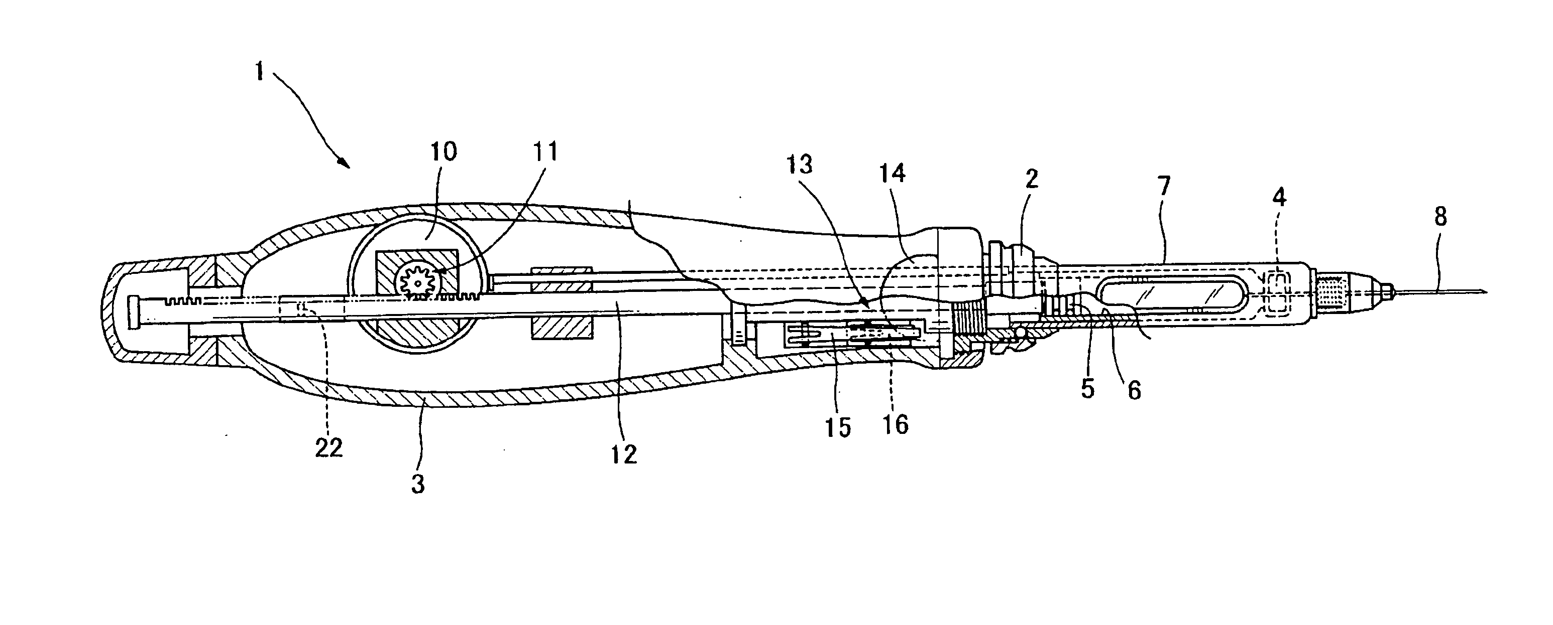
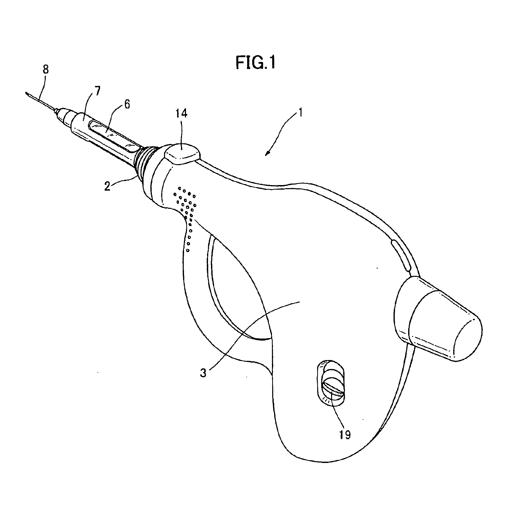
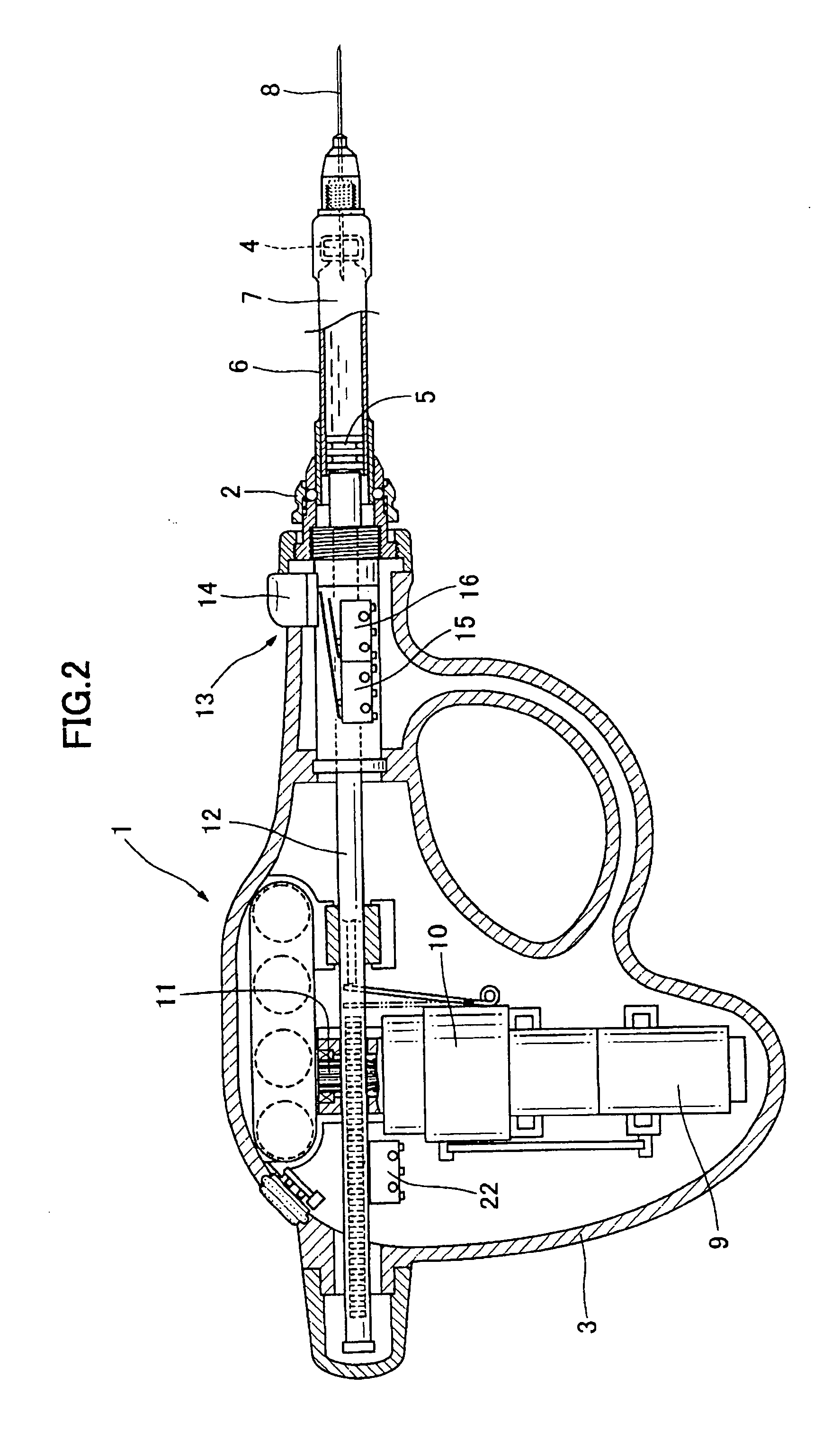
[0018]FIG. 1 shows a cartridge type motor-driven injection syringe 1 for dental use according to one embodiment of the present invention. As can be seen from FIGS. 1 and 2, the motor-driven injection syringe 1 comprises a housing 3 with a nose 2, a cartridge holder 7 to accommodate an anaesthetic solution-filled cartridge 6, which has a rubber disc 4 and a plunger rubber 5 fitted therein, a double-pointed injection needle 8 detachably attached to the end of the cartridge holder 7, penetrating the rubber disc 4; a plunger rod 12 adapted to be linearly displaced by a rack and pinion 11 operatively connected through a final reduction gear 10 to an electric motor 9, thereby ejecting the anaesthetic solution from the cartridge 6 through the injection needle 8, a starter switch 13 for starting the electric motor 9, and a button 14 for operating the starter switch 13. The starter switch 13 comprises two sequential switches 15 and 16 responsive to first and second depressions for sequential...


PUM


Abstract

Disclosed are a method and apparatus for controlling the injection rate of an anesthetic solution in a cartridge type motor-driven injection syringe for dental use, particularly beginning with the “Low” rate injection at the outset, and switching to the “Medium” or “High” injection rate at an arbitrarily selected time in the course of injection.
The speed of revolution of the electric motor is changed among the low, medium and high speed, and a two-step operable type of switch is used as a starter switch 13. The first depression of the starter switch makes the electric motor 9 start at the low speed, thereby making the plunger rubber 5 initially move at the “Low Speed” in the cartridge 6 via the plunger rod 12, and the second depression of the switch makes the electric motor 9 run at the low, medium or high speed, and accordingly the plunger rod moves at the selected “Low Speed”, “Medium Speed” or “High Speed”.

Description

BACKGROUND OF THE INVENTION [0001] 1. Field of the Invention [0002] The present invention relates to a cartridge type motor-driven injection syringe for dental use, and particularly to a method and apparatus for controlling the injection rate of a drug solution such as an anesthetic solution in a motor-driven injection syringe. [0003] 2. Prior Art [0004] The local anesthesia is indispensable for removal of gingiva, preparation of cavities, extraction of tooth and the like. Nerves to be anaesthetized run in the jaw bone or tooth, and therefore, usually the anesthetic solution is not applied directly to the nerves. In almost all cases the injection needle is inserted in the soft tissue, periodontal ligament, or near the bone close to a selected nerve, and then the anesthetic solution is locally injected, allowing the anesthetic solution to spread all over the local area, thereby making the anesthetic solution work on the nerve, which is called “Infiltration Anesthesia”. [0005] Anesthe...

Claims


Application Information

Patent Timeline
IPC IPC(8): A61M5/20
CPCA61C19/08A61M5/482A61M5/24A61M5/20
Inventor TANAKA, FUMIOKAWASAKI, YOSHIHIKOHARAGUCHI, MITSUHIROKITAGAWA, IKUOKATO, YOSHINORIHAYASHI, RENJI
Owner SHOWA YAKUHIN KAKO
Why Eureka
Try Eureka