Bendable needle assembly

a needle and distal end technology, applied in the field of needle assemblies, can solve the problems of not being useful in application in difficult to reach locations, and not being able to precisely position the open distal end of the needle in the target area of human tissu

Inactive Publication Date: 2008-04-24
ARVANAGHI BABAK
View PDF26 Cites 52 Cited by
  • Summary
  • Abstract
  • Description
  • Claims
  • Application Information

AI Technical Summary

Benefits of technology

[0007]The needle assembly according to the present invention comprises a needle including an elongated tubular needle body having open distal and proximal ends, and an elongated stylet having a solid shank complementary to the tubular needle body and slidably movable therewithin substantially coaxially thereto. The needle body includes a tip portion defining the distal end and a main portion defining the proximal end. Moreover, the tip portion bendable relative to the main portion. In turn, the stylet shank has a solid distal end. Furthermore, at least one of the distal end of the needle body and the distal end of the stylet shank is beveled at an angle to a longitudinal axis of corresponding one of the needle body and the stylet shank. The at least one beveled distal end of one of the needle body and the stylet shank exerts a bending force to the tip portion of the needle body against the beveled face during advancement of the needle body through a biological (human) tissue. As a result, the stylet controls an angle of inclination of the tip portion of the needle body relative to the main portion thereof in order to steer the needle during advancement thereof through the biological tissue.
[0008]Therefore, the present invention provides a novel needle assembly allowing for controlled steering of the needle assembly as it advances through the biological tissue in order to position a distal end of a needle exactly where needed as opposed to where is accessible with straight needles.

Problems solved by technology

For instance, as the current tubular needles are straight or curved and made of a substantially rigid (non-deformable and non-pliable) material, they have been unable to precisely position the open distal end of the needle in target areas of the human tissue, such as by bending.
Therefore they have not been useful in application for hard to reach locations in the body, while minimally invasive medical procedures are preferred in many cases.

Method used


Image

  • Bendable needle assembly
  • Bendable needle assembly
  • Bendable needle assembly

Examples


Embodiment Construction

[0031]The preferred embodiments of the present invention will now be described with the reference to accompanying drawing.

[0032]For purposes of the following description, certain terminology is used in the following description for convenience only and is not limiting. The words such as “outermost” and “innermost”, “inwardly” and “outwardly”, “left” and “right” designate directions in the drawings to which reference is made. The words “smaller” and “larger” refer to relative size of elements of the apparatus of the present invention and designated portions thereof. The terminology includes the words specifically mentioned above, derivatives thereof and words of similar import. Additionally, the word “a”, as used in the claims, means “at least one”.

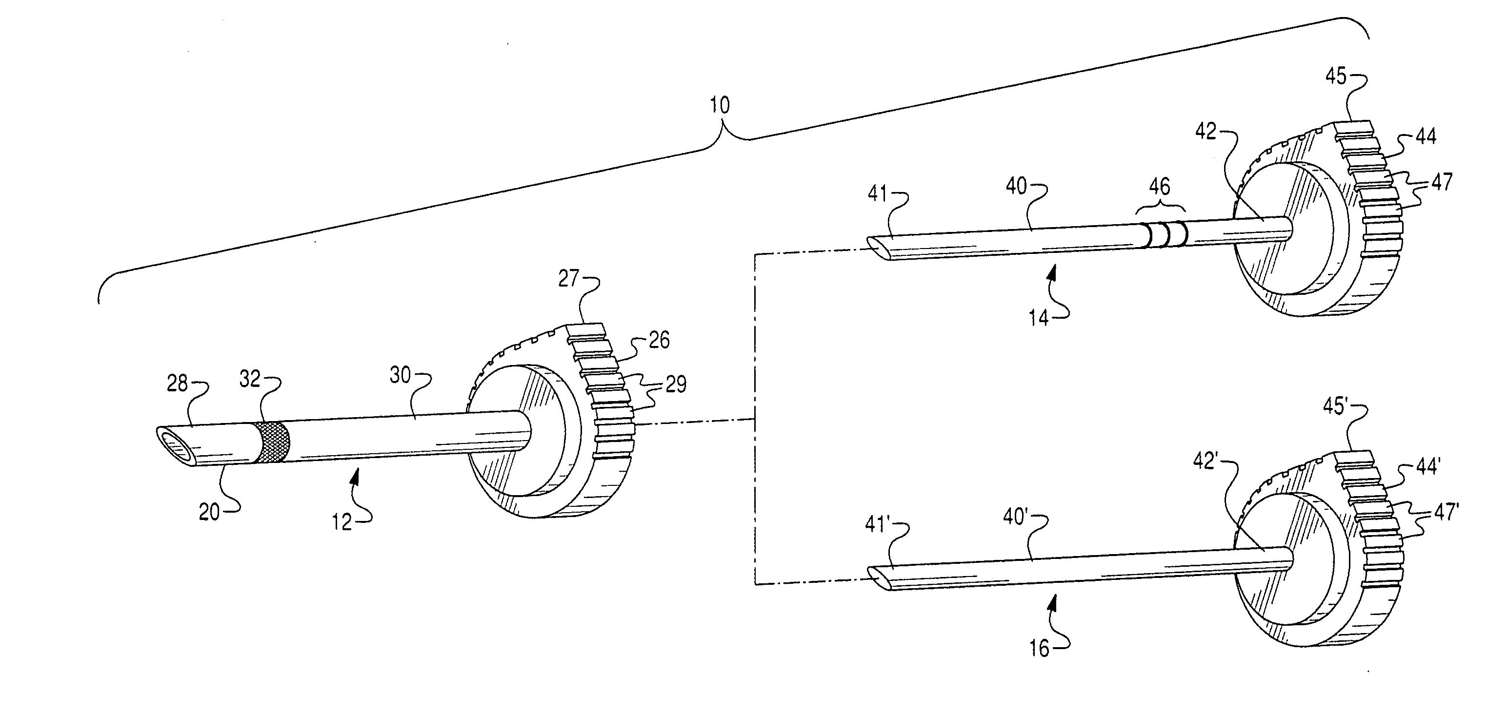
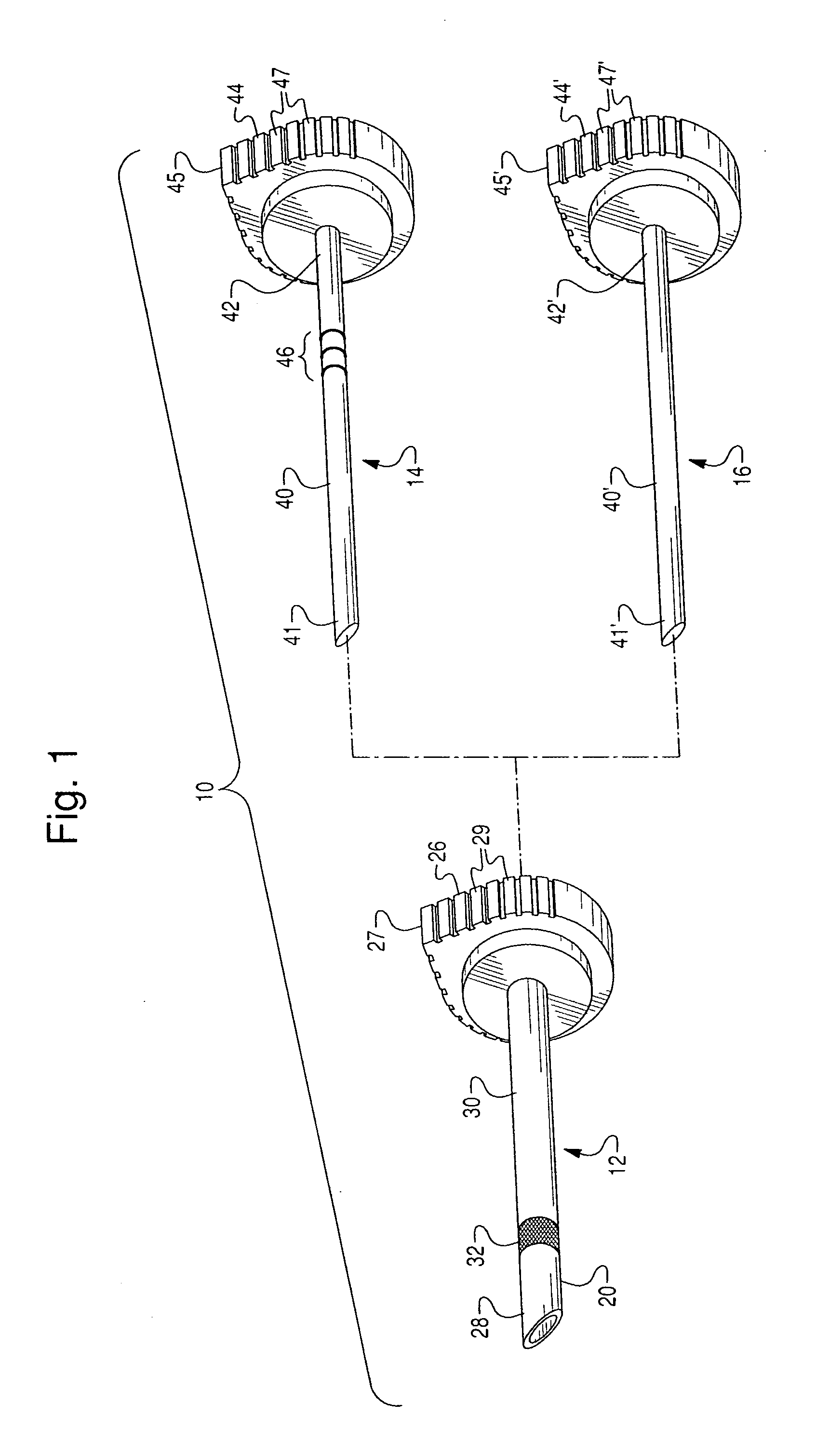
[0033]The present invention relates to a bendable needle assembly, such as a biopsy needle, epidural needle, or the like. FIGS. 1 and 5 of the drawings depict a first exemplary embodiment of the needle assembly of the present invention gen...


PUM


Abstract

The needle assembly comprises a needle including an elongated tubular needle body having open distal and proximal ends, and an elongated stylet having a solid shank complementary to the tubular needle body and slidably movable therewithin substantially coaxially thereto. The needle body includes a tip portion defining the distal end and a main portion defining the proximal end. Moreover, the tip portion bendable relative to the main portion. In turn, the stylet shank has a solid distal end. Furthermore, at least one of the distal end of the needle body and the distal end of the stylet shank is beveled at an angle to a longitudinal axis of corresponding one of the needle body and the stylet shank. The beveled distal end exerts a bending force to the tip portion of the needle body against the beveled face during advancement of the needle body through a human tissue.

Description

BACKGROUND OF THE INVENTION[0001]1. Field of the Invention[0002]This invention pertains in general to needle assemblies and, more particularly, to a needle assembly including a tubular needle and a stylet complementary to the tubular needle and provided for controlling an angle of inclination of a tip portion of the needle.[0003]2. Description of the Prior Art[0004]A large number and variety of medical needle assemblies, such as biopsy needles, epidural needles, or the like, are available and in widespread use for performing various medical procedures including but not limited to biopsy, epidural injection, disc decompression or the like. Typically, these procedures have been carried out using a hollow (tubular) needle of varying internal diameter with a tapered distal end and diagonal cutting edge. The tubular needle has the open distal end forming an axial port for placing the open distal end of the needle in target areas of a human tissue. A rod-like stylus is inserted within the...

Claims


Application Information

Patent Timeline
Patent Type & Authority Applications(United States)
IPC IPC(8): A61M5/158
CPCA61B10/0233A61B17/3401A61M2005/1581A61M5/158A61B2017/00907
Inventor ARVANAGHI, BABAK
Owner ARVANAGHI BABAK
Why Eureka
Try Eureka