
Method And System For Cardiac Signal Decomposition

a technology of cardiac signal and processing method, which is applied in the field of medical systems and methods for processing cardiac signals, can solve the problems of inability to appropriately use multi-lead packs in temporary or emergency situations, time-consuming and cumbersome placement of multiple sensors, and inability to meet the needs of medical personnel

Inactive Publication Date: 2008-04-24
SIGMED
View PDF11 Cites 64 Cited by
  • Summary
  • Abstract
  • Description
  • Claims
  • Application Information

AI Technical Summary

Problems solved by technology

However, it is time consuming and cumbersome to place multiple sensors and route their associated leads to the electrocardiogram.
Further, such multi-lead packs are costly, may not be appropriately used in temporary or emergency situations, and impractical for medical personnel unless read through a long-term ECG recording for labeling abnormal heartbeats.
When a 12-lead system can not be used, fewer leads may be applied, but there may be an associated decrease in the quality and detail in the resulting electrocardiogram recording.
Unfortunately, each channel (lead) of recorded ECG signals is typically a combination of signals from multiple sources originating from events occurring at different compartments of the heart, and strong signals such as QRS complex signals typically dominate other signals.
However, such single lead sensors typically do not provide detailed cardiac information, and are therefore useful for general evaluation only.
Since only limited information may be derived from the single lead system, an incorrect or incomplete evaluation and diagnosis may be made, which may result in long-term medical complications or even death.
Since only one channel of ECG signals is produced, signal processing methods that operate on multiple channels of input signals cannot be directly applied on 1-lead ECG signals.
However, all these manipulations have fundamental limitations associated with the linear nature, computational complexity, or difficulty in real-time implementation as well as low sensitivity and specificity.

Method used


Image

  • Method And System For Cardiac Signal Decomposition
  • Method And System For Cardiac Signal Decomposition
  • Method And System For Cardiac Signal Decomposition

Examples


Embodiment Construction

[0021] Certain embodiments of the invention are described below in connection with the drawings. It should be understood that the invention is not limited by the detailed description and the drawings, but is to be defined by the scope of the appended claims.

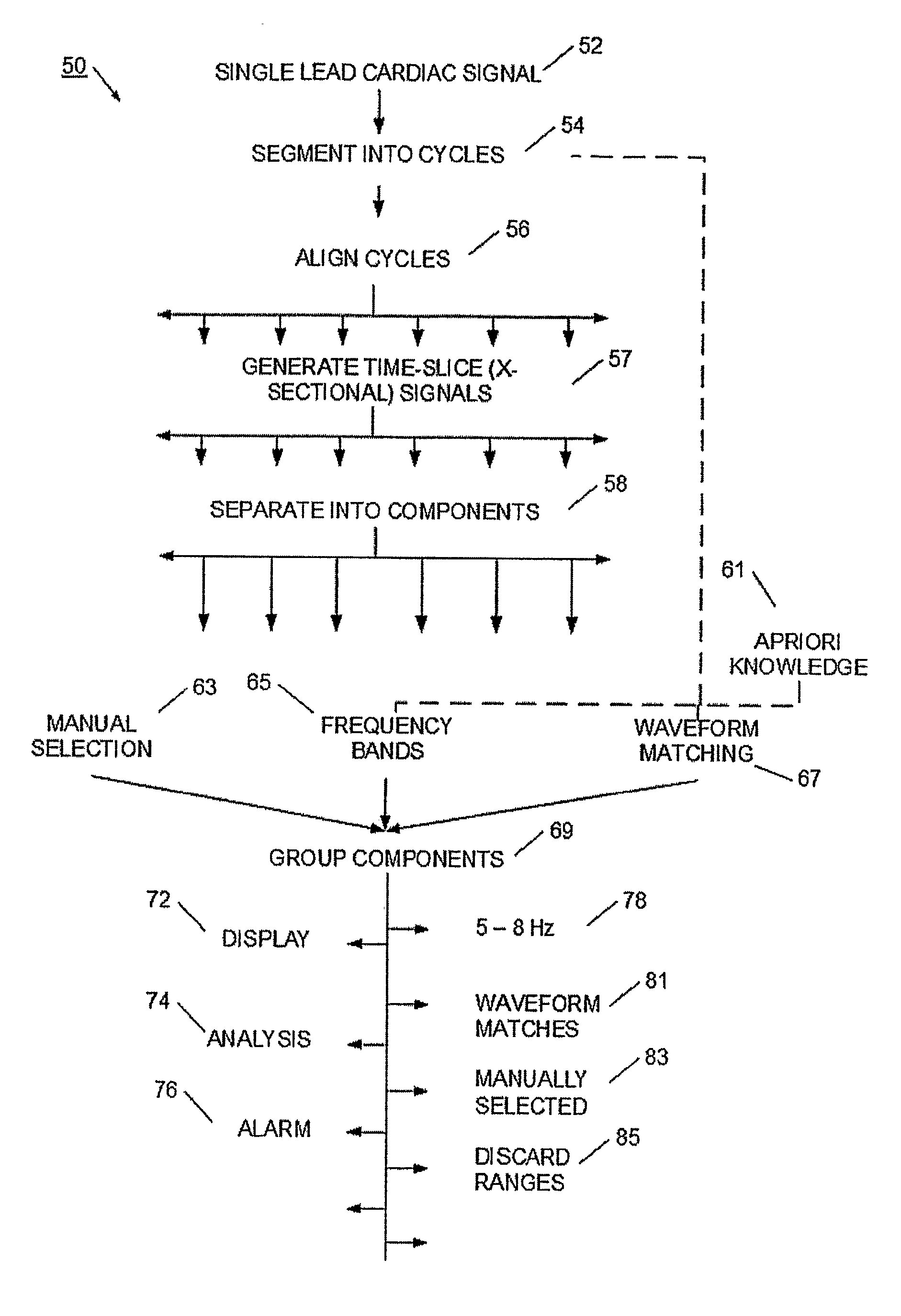
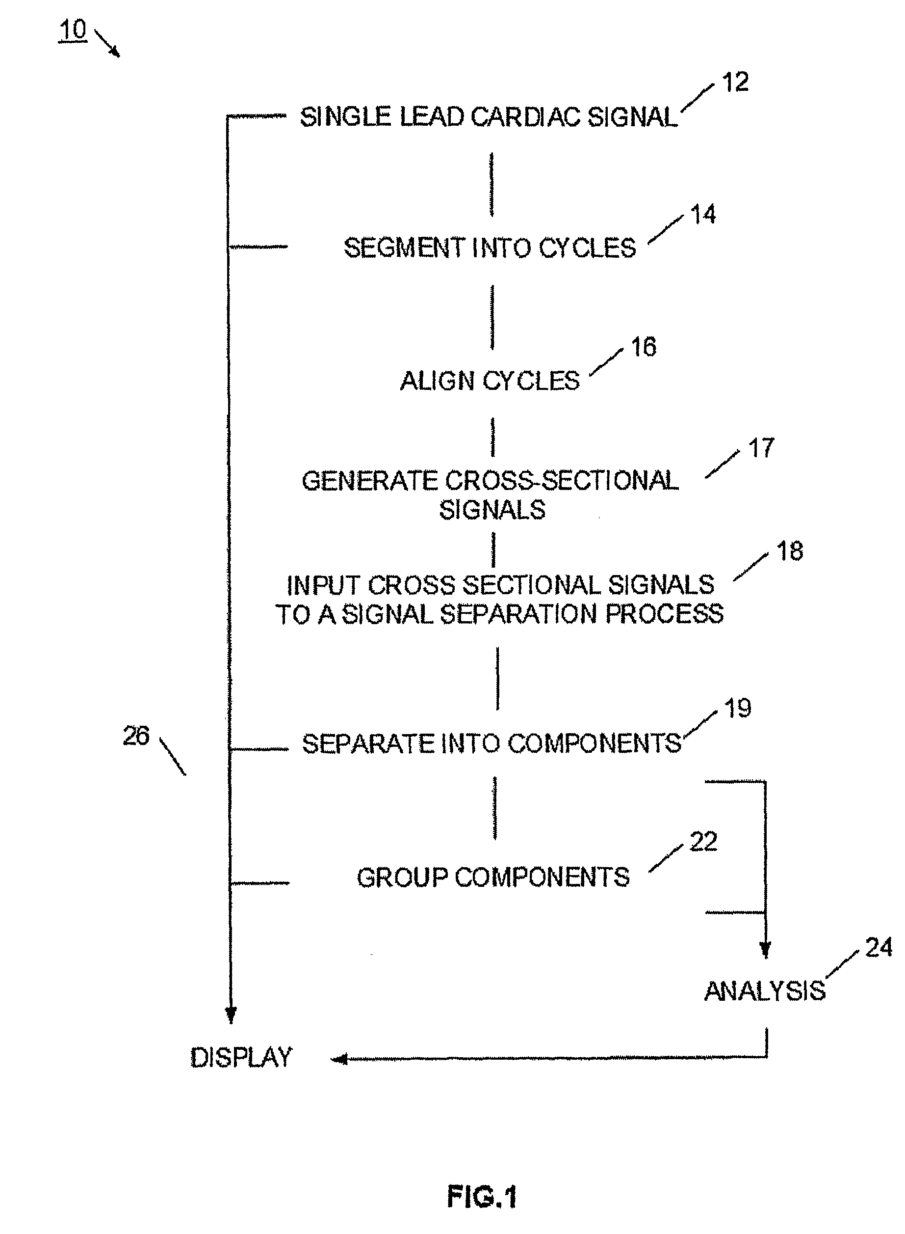
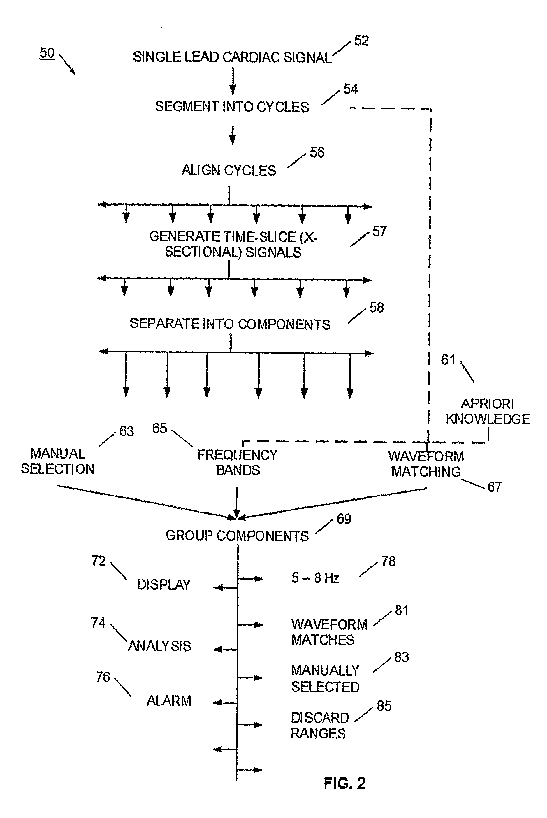
[0022] Referring to FIG. 1, a process 10 for decomposing a one-channel ECG signal is illustrated. A single-lead sensor is placed on a patient, which generates a single lead cardiac signal 12. The sensor may be part of an emergency sensor pack, associated with other medical equipment, or may even be incorporated into a device such as a pacemaker that is carried or attached to the patient. The signal 12 may be received from a patient in real-time, or may be recorded and applied to process 10 at a later time. Further, the signal 12 may be generated at one location and transmitted to another location for further processing. For example, the sensor may be attached to the patient, and a wireless radio, or other information-transmittin...


PUM


Abstract

A method and system decomposes a cardiac signal, such as an electrocardiogram (ECG) signal, into components. The components are then usable to assist in the detection of an abnormal heart condition. More particularly, a single lead sensor is used to generate a single lead cardiac signal. The cardiac signal is segmented into a set of cycle segments according to detected heart waveforms. The cycle segments are aligned and used to generate a set of cross-sectional signals. The cross-sectional signals are aligned and presented as inputs to a signal separation process, which separates the cardiac signal into a set of components. The components may be grouped according to predefined criteria. The components or groups may be analyzed or displayed to assist in the detection of an abnormal cardiac signal, which may be indicative of an abnormal heart condition. In one example, the signal separation process is a non-orthogonal transformation method such as independent component analysis (ICA).

Description

RELATED APPLICATIONS [0001] This application claims priority to U.S. provisional patent application No. 60 / 618,226, filed Oct. 13, 2004, and entitled Method and System for Cardiac Decomposition, which is incorporated herein by reference.FIELD OF THE INVENTION [0002] The present invention relates to the field of medical systems and methods for processing cardiac signals. More particularly, the present invention relates to the application of a signal separation process to electrocardiogram signals. DESCRIPTION OF THE RELATED ART [0003] An electrocardiogram (ECG / EKG) is an electrical recording of the heart and is used in the investigation of heart disease. The measurements taken are utilized in making an interpretation typically of rate / rhythm analysis and / or morphology. The measurements can be used to determine such features as the underlying rate and rhythm mechanism of the heart, the orientation of the heart (how it is placed) in the chest cavity, evidence of increased thickness (hy...

Claims


Application Information

Patent Timeline
IPC IPC(8): A61N1/368
CPCA61B5/0452A61B5/349
Inventor DUANN, JENG-RENJUNG, TZYY-PING
Owner SIGMED
Learn More