
Drain cleaning machine with added stability, portability and maneuverability

a technology of maneuverability and drain cleaning machine, which is applied in the direction of sewer cleaning, sewer systems, construction, etc., can solve the problems of reducing the stability of the machine, and reducing the overall size or footprint of the machine, so as to facilitate the movement of the drain cleaning apparatus

Inactive Publication Date: 2008-05-01
EMERSON ELECTRIC CO
View PDF9 Cites 34 Cited by
  • Summary
  • Abstract
  • Description
  • Claims
  • Application Information

AI Technical Summary

Benefits of technology

[0005]The drain cleaning apparatus discussed above can also include a movable member connected to the frame member and selectively movable between a first position and a second position. The movable member includes a handle portion configured for gripping when the movable member is in the first position. The movable member also includes a surface engaging portion configured to contact the associated surface when the movable member is in the second position. Moving the movable member into the second position can provide stability by moving the center of gravity of the machine and also reduce the overall height of the machine for easy storage.

Problems solved by technology

These machines can be very heavy and difficult to move; however, these machines still need to be moved to a location near the drain that needs to be cleaned.
The addition of wheels to such a drain cleaning machine, however, can reduce its stability and also increase the overall size or footprint of the machine.
Handles can be added to assist moving the machine, but overall size (height) then becomes an issue for storage.
Moreover, the addition of wheels and handles to the drain cleaning machine does not mitigate the difficulty of traversing staircases.

Method used


Image

  • Drain cleaning machine with added stability, portability and maneuverability
  • Drain cleaning machine with added stability, portability and maneuverability
  • Drain cleaning machine with added stability, portability and maneuverability

Examples


Embodiment Construction

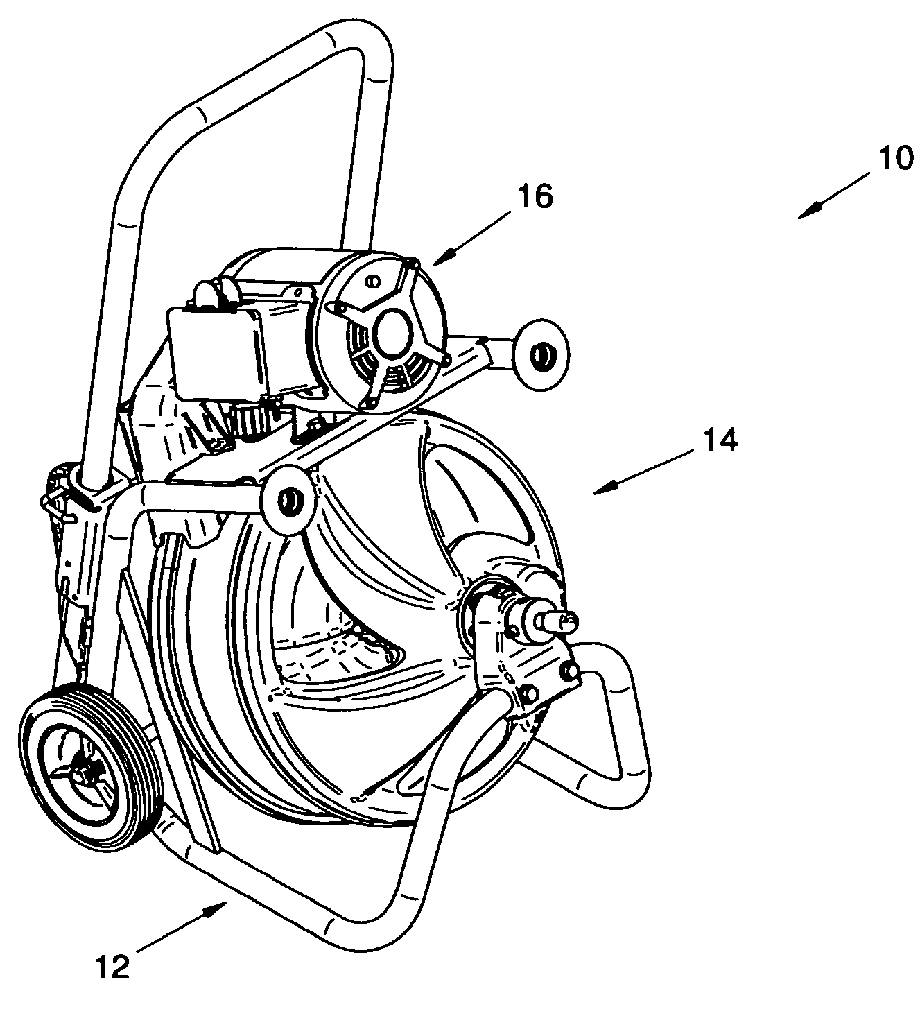
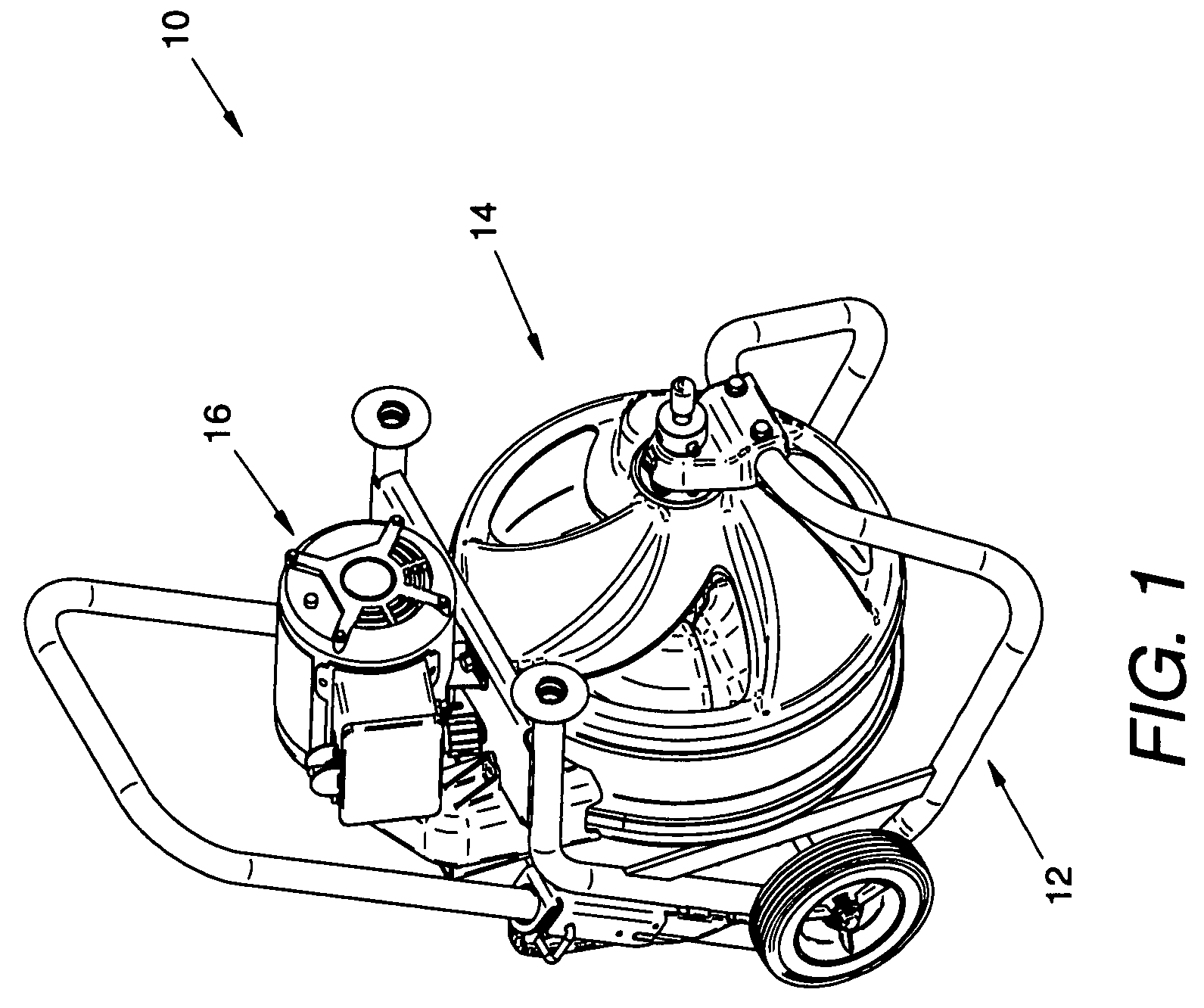
[0018]With reference to FIG. 1, a drain cleaning apparatus 10 includes a frame assembly 12, a rotatable drum unit 14 and a drum driving assembly 16. The drain cleaning apparatus depicted in FIG. 1 is very portable and can easily traverse stairs.

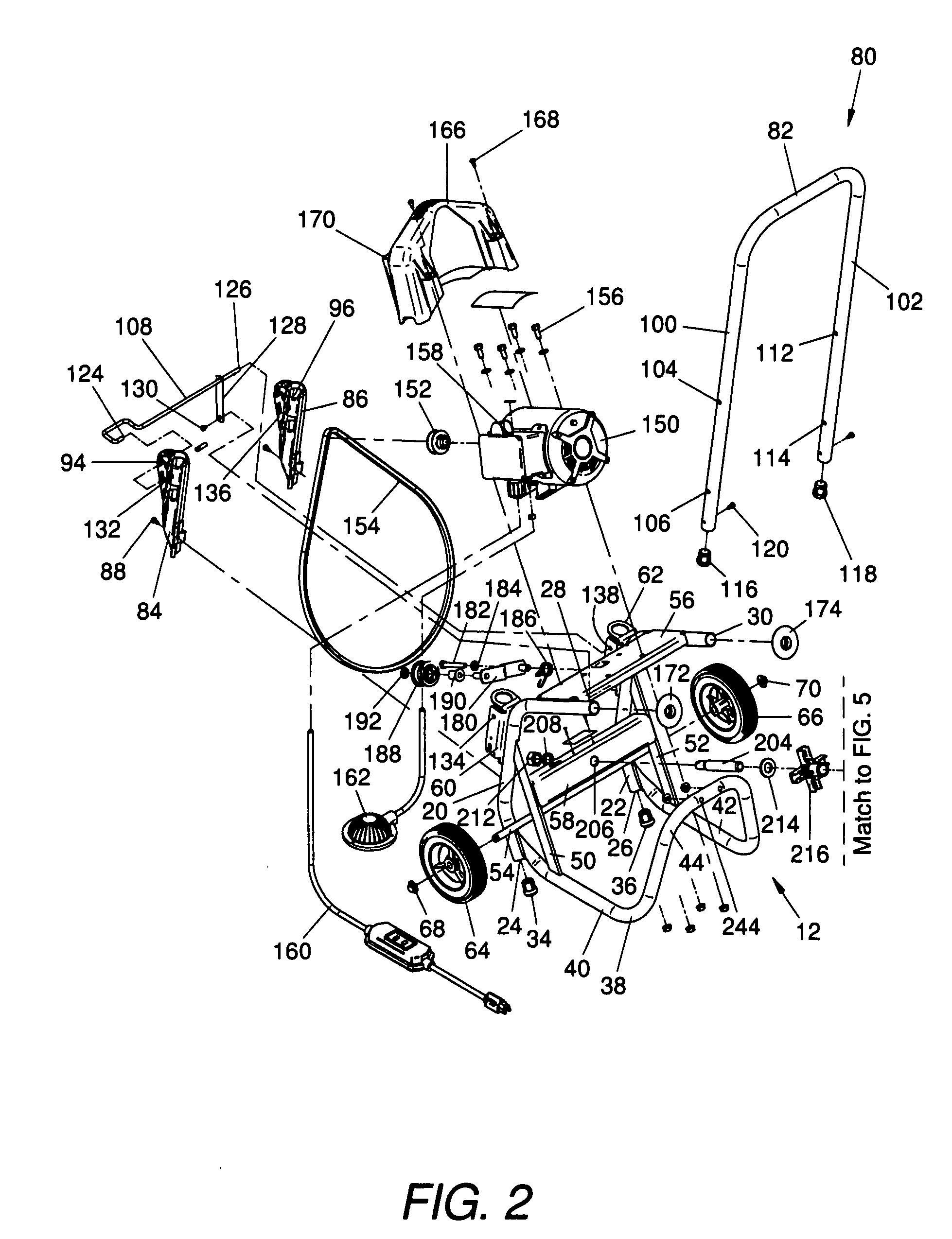
[0019]With reference to FIG. 2, the frame assembly 12 generally includes first and second spaced arm members 20 and 22. The arm members are made from tubular metal stock or similar materials and each include first (lower) ends 24 and 26, respectively, and second (upper) ends 28 and 30, respectively. The lower portion of each arm member 20 and 22 includes a bend so that the lower ends 24 and 26, respectively, are located nearer to the drum unit 14. A first foot 34 connects with the first, or lower, ends 24 of the first arm member 20. Similarly, a second foot 36 connects with the first end 26 of the second arm member 22. The feet 34 and 36 are made of rubber, plastic, or similar material.

[0020]A U-shaped member 38 attaches to the first arm memb...


PUM


Abstract

A drain cleaning apparatus includes a frame member, a rotatable cable storage drum, a drain cleaning cable, and a motor. The frame member is configured to rest on an associated surface. A wheel, or other friction reducing device, can connect to the frame member to facilitate moving the drain cleaning apparatus across the associated surface. The rotatable cable storage drum mounts to the frame member. The drum defines an axis. The drum includes axially spaced front and rear ends and a radial outer peripheral wall between the front and rear ends. The front end of the drum includes an opening. The drain cleaning cable is coiled in the drum about the axis. The cable includes an outer end portion extending through the opening. The motor includes an output shaft and a motor housing. The output shaft of the motor is operatively connected with the drum for rotating the drum relative to the frame.

Description

BACKGROUND[0001]Machines used to clean drain pipes typically include a drum having a cable, or snake, coiled within the drum. The drum is rotated by an endless belt trained about a motor driven pulley and the outer periphery of the drum or a drum mounted pulley. These machines can be very heavy and difficult to move; however, these machines still need to be moved to a location near the drain that needs to be cleaned.[0002]Wheels can be provided with these drain cleaning machines so that they are portable. The addition of wheels to such a drain cleaning machine, however, can reduce its stability and also increase the overall size or footprint of the machine. Handles can be added to assist moving the machine, but overall size (height) then becomes an issue for storage. Moreover, the addition of wheels and handles to the drain cleaning machine does not mitigate the difficulty of traversing staircases.BRIEF DESCRIPTION[0003]A drain cleaning apparatus includes a frame member, a rotatable...

Claims


Application Information

Patent Timeline
IPC IPC(8): B08B9/02
CPCE03F9/005B08B9/045
Inventor RUTKOWSKI, MICHAEL J.DUNKIN, JON R.BABB, LARRY F.
Owner EMERSON ELECTRIC CO
Features
  • Generate Ideas
  • Intellectual Property
  • Life Sciences
  • Materials
  • Tech Scout
  • Unparalleled Data Quality
  • Higher Quality Content
  • 60% Fewer Hallucinations
Learn More