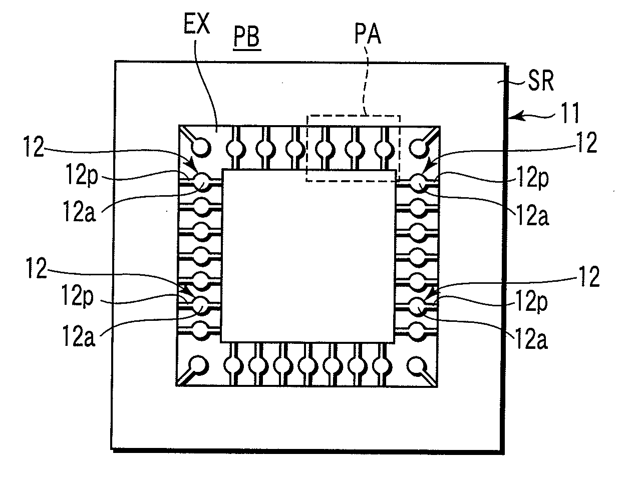
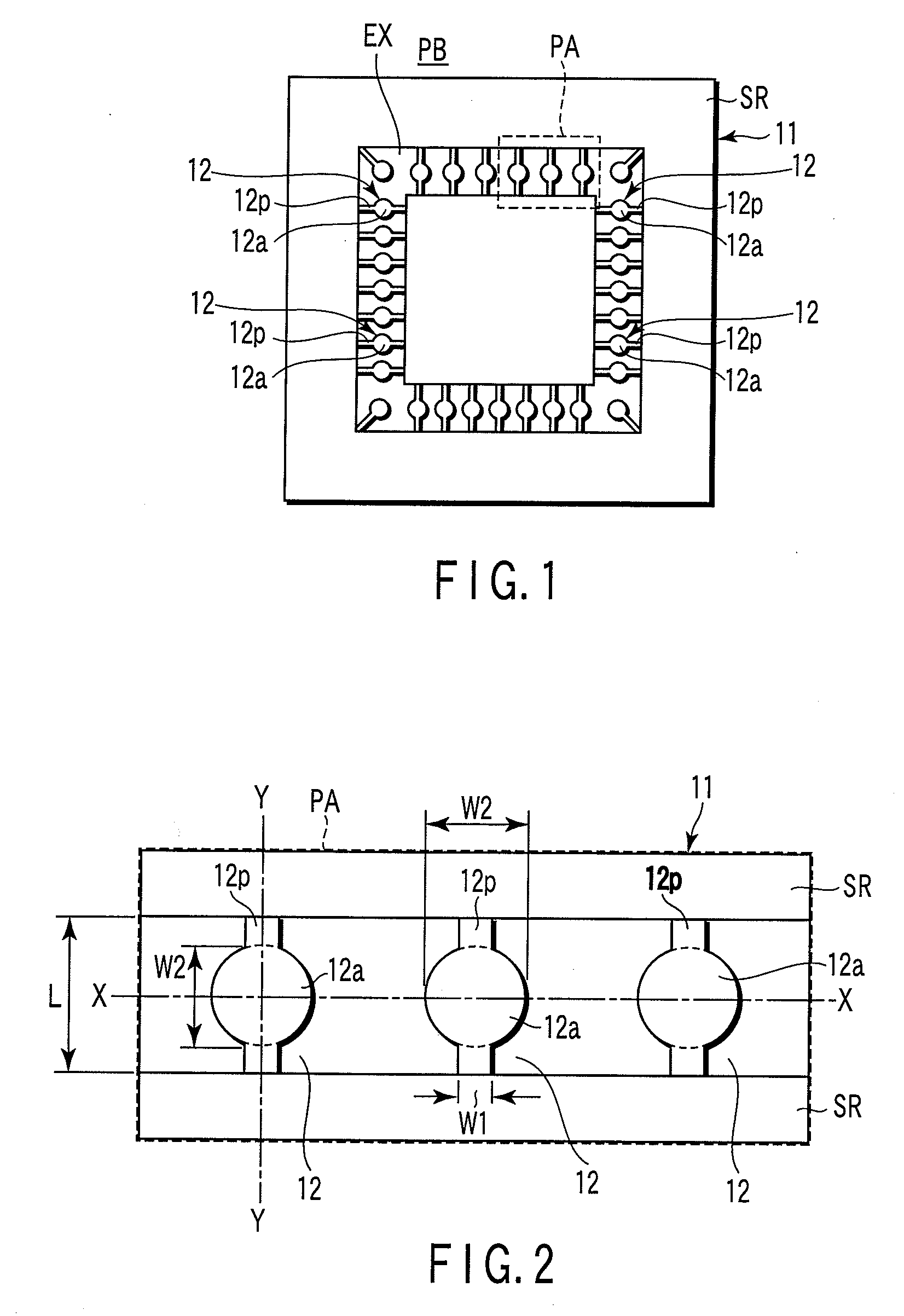
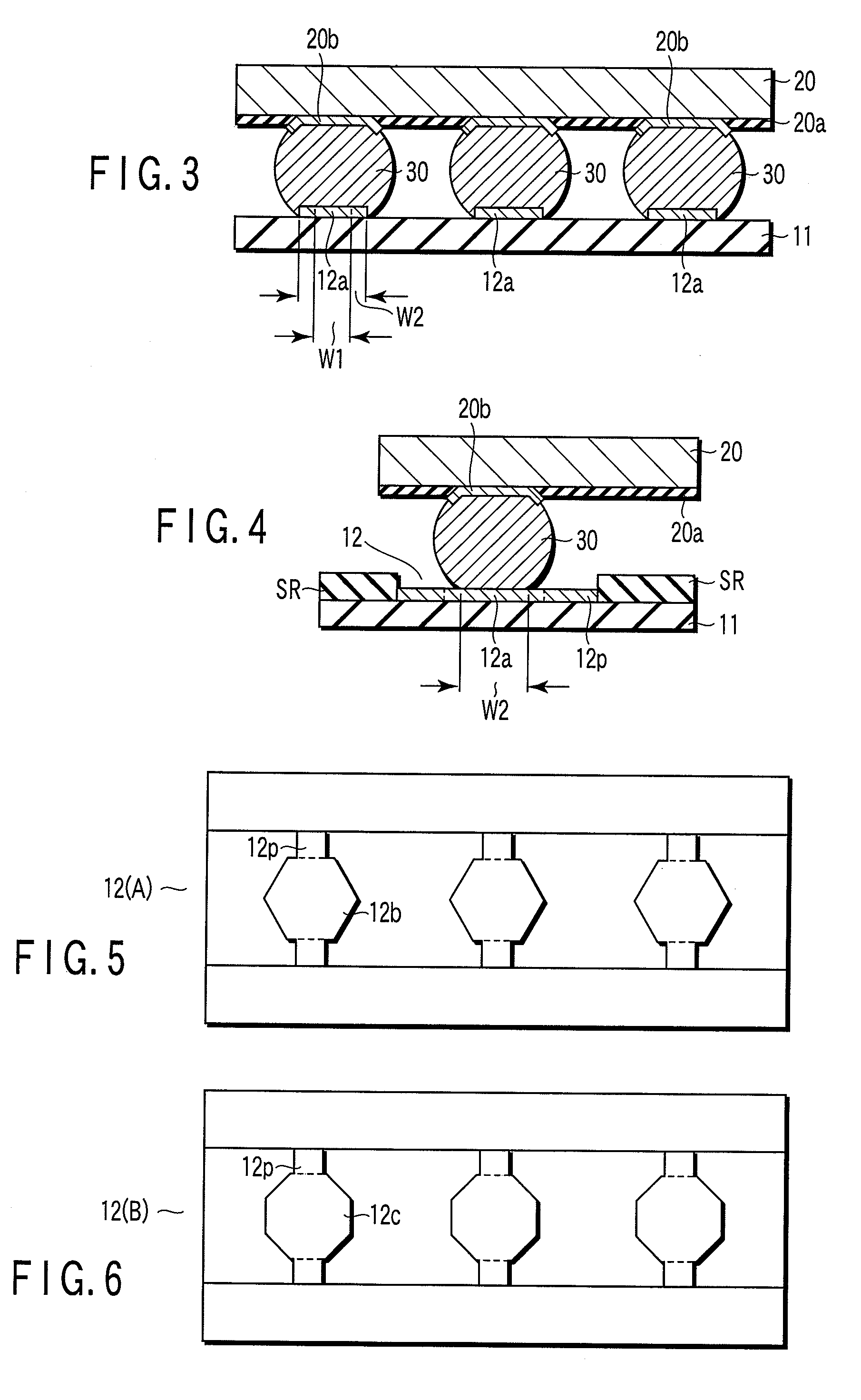
Printed-wiring board, method for forming electrode of the board, and hard disk device

a technology of printed wiring and electrodes, applied in the direction of sustainable manufacturing/processing, instruments, final product manufacturing, etc., can solve the problems of hard to apply solder bonding to mount bare chips, clacking at solder bonding parts,

Inactive Publication Date: 2008-05-01
KK TOSHIBA
View PDF3 Cites 24 Cited by
  • Summary
  • Abstract
  • Description
  • Claims
  • Application Information

AI Technical Summary

Problems solved by technology

The accumulation of the stress will cause an occurrence of a clack at the solder bonding part.
This technique is applicable to a semiconductor device of a type in which an IC chip such as a QFP is coated with a mold resin, but hard to apply it to mount a bare chip which requires electrode processing for forming electrodes arranged with a microscopic pitch.

Method used


Image

  • Printed-wiring board, method for forming electrode of the board, and hard disk device
  • Printed-wiring board, method for forming electrode of the board, and hard disk device
  • Printed-wiring board, method for forming electrode of the board, and hard disk device

Examples


Embodiment Construction

[0021]Various embodiments according to the invention will be described hereinafter with reference to the accompanying drawings.

[0022]An embodiment of the present invention will be described hereinafter with reference to the accompanying drawings. FIG. 7 depicts a configuration of a hard disk device with a circuit board configured by using a printed-wiring board regarding the present invention mounted thereon.

[0023]A hard disk device 8 is configured to include a device main body 10, and a control circuit board 11.

[0024]The main body 10 includes a case 17 having an upper wall 17a, a lower wall 17b, and a side wall 17c, and a magnetic disk 21, a spindle motor 22, a magnetic head 23, a head actuator 24, a voice coil motor 25, etc., stored in the case 17.

[0025]The control circuit board 11 has engaging halls h which engage with protruded parts (not shown) protruded from the lower wall 17b of the main body 10, and is mounted on the exterior lower surface part of the case 17 in a state in w...


PUM

PropertyMeasurementUnit
widthaaaaaaaaaa
widthaaaaaaaaaa
lengthaaaaaaaaaa

Abstract

According to one embodiment, there is provided a printed-wiring board on which an electrode for a semiconductor device bonding in a flip-chip-mounting manner is formed by an exposed part of a wiring pattern defined by a solder resist coating film, wherein the electrode includes an expanded section spreading in a line width direction of the wiring pattern to form the electrode.

Description

CROSS-REFERENCE TO RELATED APPLICATIONS[0001]This application is based upon and claims the benefit of priority from Japanese Patent Application No. 2006-296924, filed Oct. 31, 2006, the entire contents of which are incorporated herein by reference.BACKGROUND[0002]1. Field[0003]One embodiment of the present invention relates to a printed-wiring board having electrodes on which a semiconductor device is to be flip-chip-bonded, each of the electrodes being formed at an exposed portion of a wiring pattern defined by a solder resist coating film.[0004]2. Description of the Related Art[0005]In a small-sized electronic equipment to be easily carried, a technique for mounting a semiconductor device such as a bare chip on a circuit board inside the equipment by flip-chip bonding has become widely used. As to a printed-wiring board used in a circuit board, a printed-wiring board having electrodes to be used for flip-chip bonding is used, in which the electrodes are formed at an exposed portio...

Claims


Application Information

Patent Timeline
Patent Type & Authority Applications(United States)
IPC IPC(8): H05K1/11H05K3/00G11B21/02
CPCH01L23/49816H01L23/49838H01L2224/81801H01L2924/15173Y10T29/49149H05K3/3452H05K2201/09381H05K2201/0989H05K2201/10674H05K1/111G11B5/4846G11B21/02Y02P70/50
Inventor HIRAMOTO, SYUJIAOKI, MAKOTO
Owner KK TOSHIBA
Why Eureka
Try Eureka