This helps you quickly interpret patents by identifying the three key elements:
Problems solved by technology
Method used
Benefits of technology
Benefits of technology
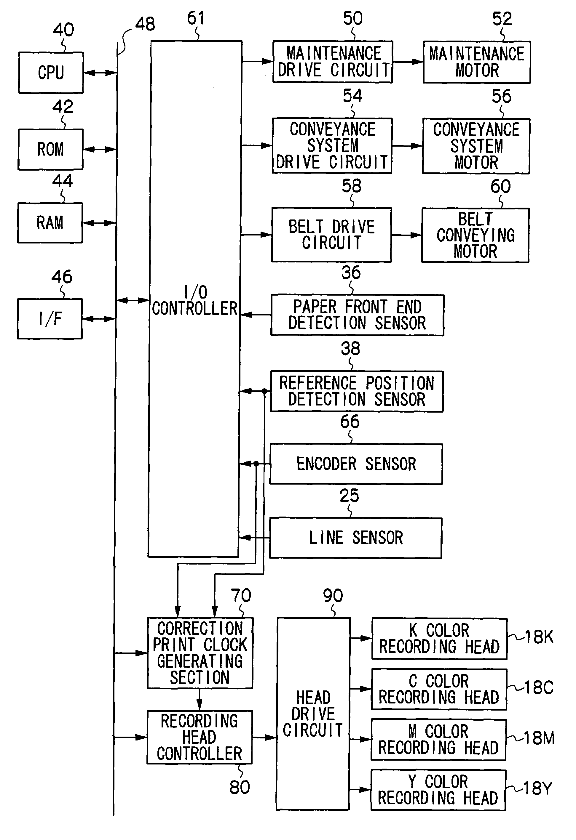
[0010]According to an aspect of the invention, there is provided a droplet ejecting apparatus comprising: a droplet ejecting head for ejecting droplets onto a recording medium; a moving unit for moving the recording medium relative to the droplet ejecting head; an output unit for outputting a pulse signal which is generated along with moving of the moving unit and which has a pulse width comprising a cyclic fluctuation; a reference position detection unit for detecting a reference position in the cyclic fluctuation; a pattern memory for storing image information of a detection pattern comprising plural unit patterns which are set in advance; a reading unit for reading an image formed on the recording medium; a detection pattern output unit that drives the droplet ejecting head based on the pulse signal outputted from the output unit and the image information of the detection pattern stored in the pattern memory when a detection pattern output instruction is present; a correction information generating unit that makes the reading unit read an image on the recording medium on which the detection pattern image is form
Problems solved by technology
The drive roll contains eccentric error due to manufacturing reason.
The cord wheel also contains installation error and a print error of the mark thereon.
For the reason, cyclic mismatch is generated between an encodersignal for use in print clock and conveyance velocity of the recording medium so that the ejection timing deviates, thereby causing a deviation in a droplet shot position on a paper.
Method used
Image
Click on the blue label to locate the original text in one second.
Reading with bidirectional positioning of images and text.
Examples
first exemplary embodiment
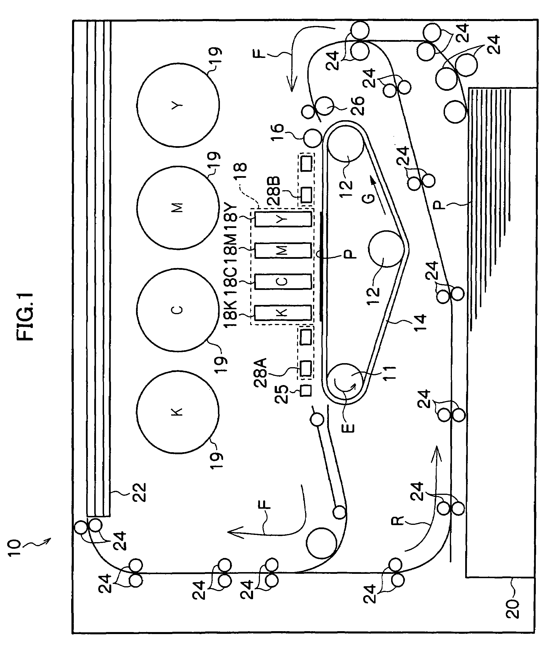
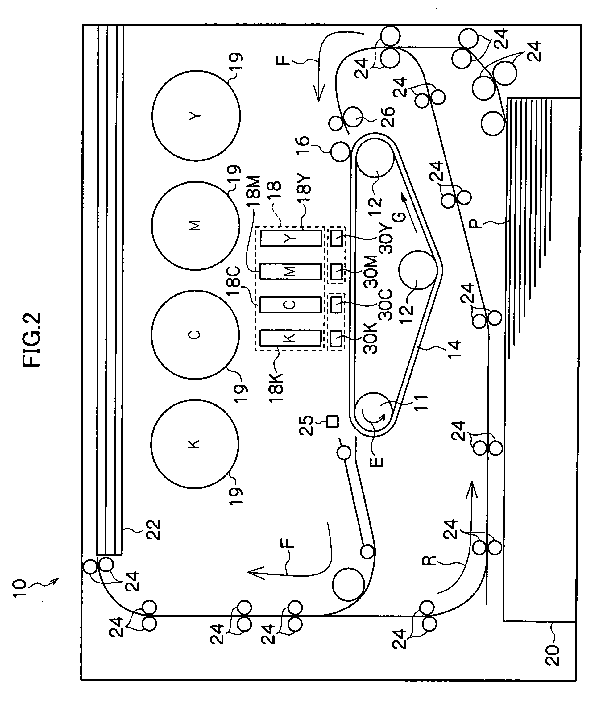
[0027]FIG. 1 schematically shows the structure of the image forming apparatus 10 according to the exemplary embodiment of the invention. As shown in the FIG. 1, the image forming apparatus 10 includes a paper feed tray 20, an exit tray 22 and plural rollers 24.
[0028]Recording papers P are accommodated in the paper feed tray 20. When an image is formed, the recording papers P are picked up one by one from the paper feed tray 20 by the rollers 24, and conveyed along a predetermined conveyance passage F within the image forming apparatus 10 and ejected into the exit tray 22.
[0029]A conveyance belt 14 and a adherence unit 16 are disposed along the conveyance passage F of this recording paper P. The conveyance belt 14 is stretched around a drive roll 11 which rotates in the direction of an arrow E and two driven rolls 12 which rotate following the rotation of the drive roll 11, and the conveyance belt 14 rotates in the direction of an arrow G. The adherence unit 16 presses the recording ...
first modification
(First Modification)
[0098]In the first exemplary embodiment, the example of starting printing of the deviation detection pattern A based on a timing when the reference position is detected after a paper front end is detected in the creation processing of the correction table has been described. Hereinafter, as a first modification, an example of starting printing of the deviation detection pattern A based on a timing when the paper front end is detected will be described.
[0099]The deviation detection pattern A printed at the head of the recording paper P is not limited to A0 as shown in FIG. 11. Thus, in the first modification, the detection mark R is printed at a timing when the reference position is detected. As shown in FIG. 11, the detection mark R is printed in an area different from the print area from the deviation detection pattern A.
[0100]The CPU 40 specifies the printed deviation detection pattern A whose recording paper conveyance direction position is the same as the det...
second modification
(Second Modification)
[0102]If the deviation detection patterns A in an amount larger than the number corresponding to a single turn are printed, plural correction values Q are obtained in each step. Therefore, an actual correction value q may be derived based on the plural correction values Q.
[0103]At cycle joint portion indicated with a dotted line frame in FIG. 12, there is a tendency that a large difference exists. To reduce this difference to smoothen the joint, averaging procedure may be performed.
[0104]At this time, the plural correction values Q may be averaged simply as they are or may be averaged after weighting.
PUM
Abstract
In a droplet ejecting apparatus, a detection pattern output unit drives a droplet ejecting head based on a pulse signal and image information of a detection pattern comprising plural unit patterns so as to form an image of the detection pattern on a recording medium. A correction information generating unit derives a distance between adjacent unit patterns based on the image of a read detection pattern, compares the distance with a distance according to the conveyance velocity of the recording medium by a moving unit, and generates correction information so as to enlarge the pulse width when the derived distance is shorter, and to reduce the pulse width when the derived distance is longer.
Description
CROSS-REFERENCE TO RELATED APPLICATIONS[0001]This application is based on and claims priority under 35 USC 119 from Japanese Patent Application No. 2006-296170 filed Oct. 31, 2006.BACKGROUND OF THE INVENTION[0002]1. Technical Field[0003]The present invention relates to a droplet ejecting apparatus.[0004]2. Related Art[0005]The droplet ejecting apparatus such as an ink jet printer forms an image by driving a recording head according to image data and ejecting ink droplets onto a recording medium from nozzles of the recording head.[0006]In some recording head adopting full width array (FWA) technology in which plural nozzles are arranged on scanning lines throughout the entire width of the recording medium, for example, a cord wheel is attached on a rotation shaft of a drive roll for conveying the recording medium and a signal obtained by reading a mark on the cord wheel by an optical sensor is used for droplet ejection timing control.[0007]The drive roll contains eccentric error due ...
Claims
Application Information
Patent Timeline
Application Date:The date an application was filed.
Publication Date:The date a patent or application was officially published.
First Publication Date:The earliest publication date of a patent with the same application number.
Issue Date:Publication date of the patent grant document.
PCT Entry Date:The Entry date of PCT National Phase.
Estimated Expiry Date:The statutory expiry date of a patent right according to the Patent Law, and it is the longest term of protection that the patent right can achieve without the termination of the patent right due to other reasons(Term extension factor has been taken into account ).
Invalid Date:Actual expiry date is based on effective date or publication date of legal transaction data of invalid patent.

