Ultrasound measurement apparatus

a measurement apparatus and ultrasound technology, applied in the field of ultrasound measurement apparatus, can solve the problem that the width of the chirp signal cannot be significantly long, when detecting slow movement, and achieve the effect of not increasing the pulse width

Inactive Publication Date: 2005-07-19
JAPAN SCI & TECH CORP
View PDF8 Cites 16 Cited by
  • Summary
  • Abstract
  • Description
  • Claims
  • Application Information

AI Technical Summary

Benefits of technology

[0010]According to the above configuration, the measurement apparatus of the present invention is capable of performing measurement without increasing pulse width by dividing and then multiplexing the chirp signal spectrum.

Problems solved by technology

However, since the detectable frequency displacement corresponds to the time-average of the chirp signal width, chirp signal width cannot be significantly long when detecting slow movement.

Method used


Image

  • Ultrasound measurement apparatus
  • Ultrasound measurement apparatus
  • Ultrasound measurement apparatus

Examples


Embodiment Construction

[0020]The embodiments of the present invention are described in detail while referencing the drawings.

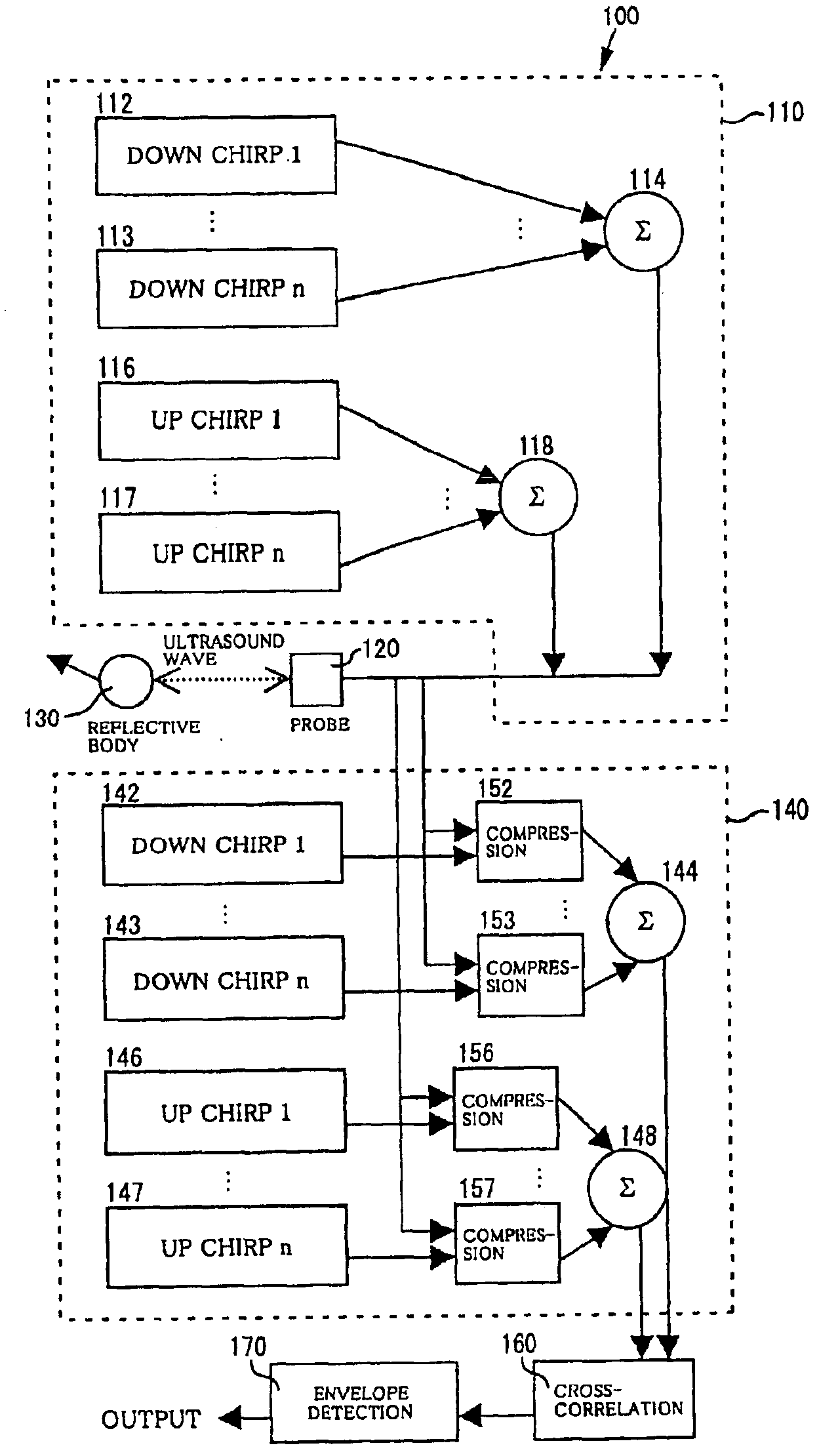
[0021]The present invention is one to perform measurement through dividing and then multiplexing the chirp signal spectrum, rather than increasing pulse width.

[Doppler Measurement Apparatus]

[0022]An embodiment where velocity is measured through utilizing the Doppler effect using up chirp and down chirp signals is described.

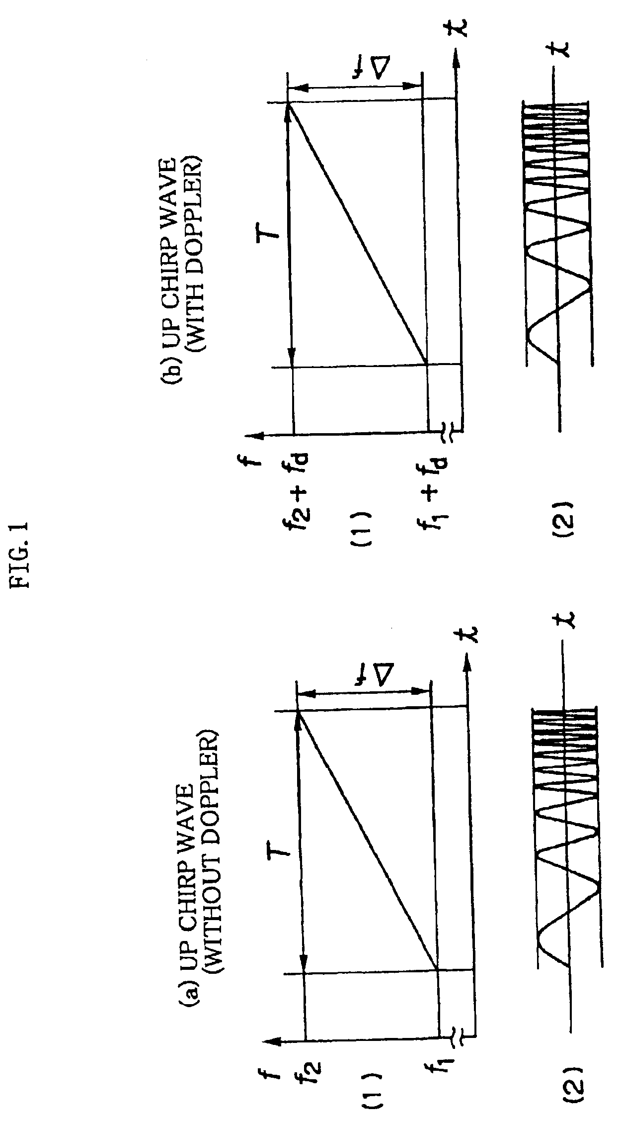
[0023]The up chirp and down chirp signals used in Doppler measurement and the Doppler effect for these signals are described using FIG. 1 through FIG. 4.

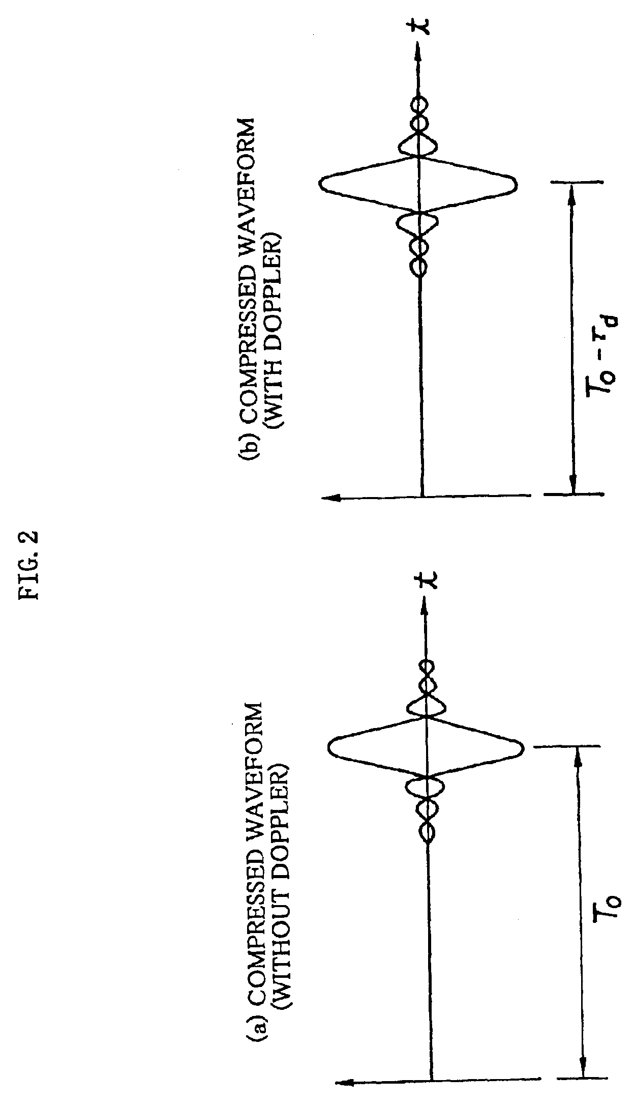
[0024]To begin with, the case with the up chirp signal is considered. A case where there is no Doppler effect is first described. FIG. 1(a) is a diagram schematically illustrating a linear FM chirp signal, which is a chirp signal with pulse width T and the frequency of which shows a linear increase from f1 to f2=f1+Δf. When the chirp signal is compressed it becomes a waveform as illustrated in FIG. 2(a). At this p...


PUM


Abstract

An ultrasound wave is transmitted from a probe (120) to a moving reflector (130) and the reflected ultrasound wave is received back by the same probe (120). With n-divided wave bands of the to-be-used spectrum, the ultrasound wave to be transmitted is made up of up chirp signals and down chirp signals from n number of down chirp signal generators (112, 113) and up chirp signal generators (116, 117), creating complementary multiplexed chirp signals through synthesizers (114, 118). Cross-correlation is taken by a correlator between the reception signal received at the probe (120) and the up chirp and the down chirp signals, respectively, so as to provide compressed up and down signals and then combining the obtained compressed signals through synthesizers (144, 148). Doppler measurement is performed by determining the correlation distance through taking the cross-correlation between these compressed signals by a cross-correlator (160) and performing envelope detection by an envelope detector (170).

Description

TECHNICAL FIELD[0001]The present invention relates to a measurement apparatus utilizing ultrasound. In particular, it is related to a measurement apparatus using chirp signals.BACKGROUND ART[0002]Conventionally, measurement has been performed and images obtained utilizing reflected ultrasound waves and the like. For example, with an ultrasound diagnosis apparatus, a tomogram of an organism is obtained by transmitting an impulse wave from an ultrasound transducer, receiving back the reflected echo, and then subjecting it to image processing. For such an ultrasound diagnosis apparatus, the deepest invasion depth and highest resolution possible is required.[0003]There is a pulse compression technique that satisfies this requirement. With this, an originally long pulse is compressed and therefore shortened by subjecting a to-be-transmitted ultrasound signal to FM modulation (hereinafter, the resulting signal is referred to as a chirp signal) and upon reception, passing it through a filt...

Claims


Application Information

Patent Timeline
Patent Type & Authority Patents(United States)
IPC IPC(8): G01S15/89G01S15/00G01S15/34A61B8/06G01B17/00A61B8/08A61B8/14G01S15/10
CPCG01S15/8954G01S15/8961G01S15/8979G01S15/34
Inventor MORIYA, TADASHITANAHASHI, YOSHIKATSUYOSHIZAWA, MASASUMI
Owner JAPAN SCI & TECH CORP
Why Eureka
Try Eureka