

Display apparatus
a technology of display apparatus and display screen, which is applied in the direction of instruments, static indicating devices, etc., can solve the problem of difficult to preferably emit accumulated charges
- Summary
- Abstract
- Description
- Claims
- Application Information
AI Technical Summary
Benefits of technology
Problems solved by technology
Method used
Image

Examples
embodiment 1
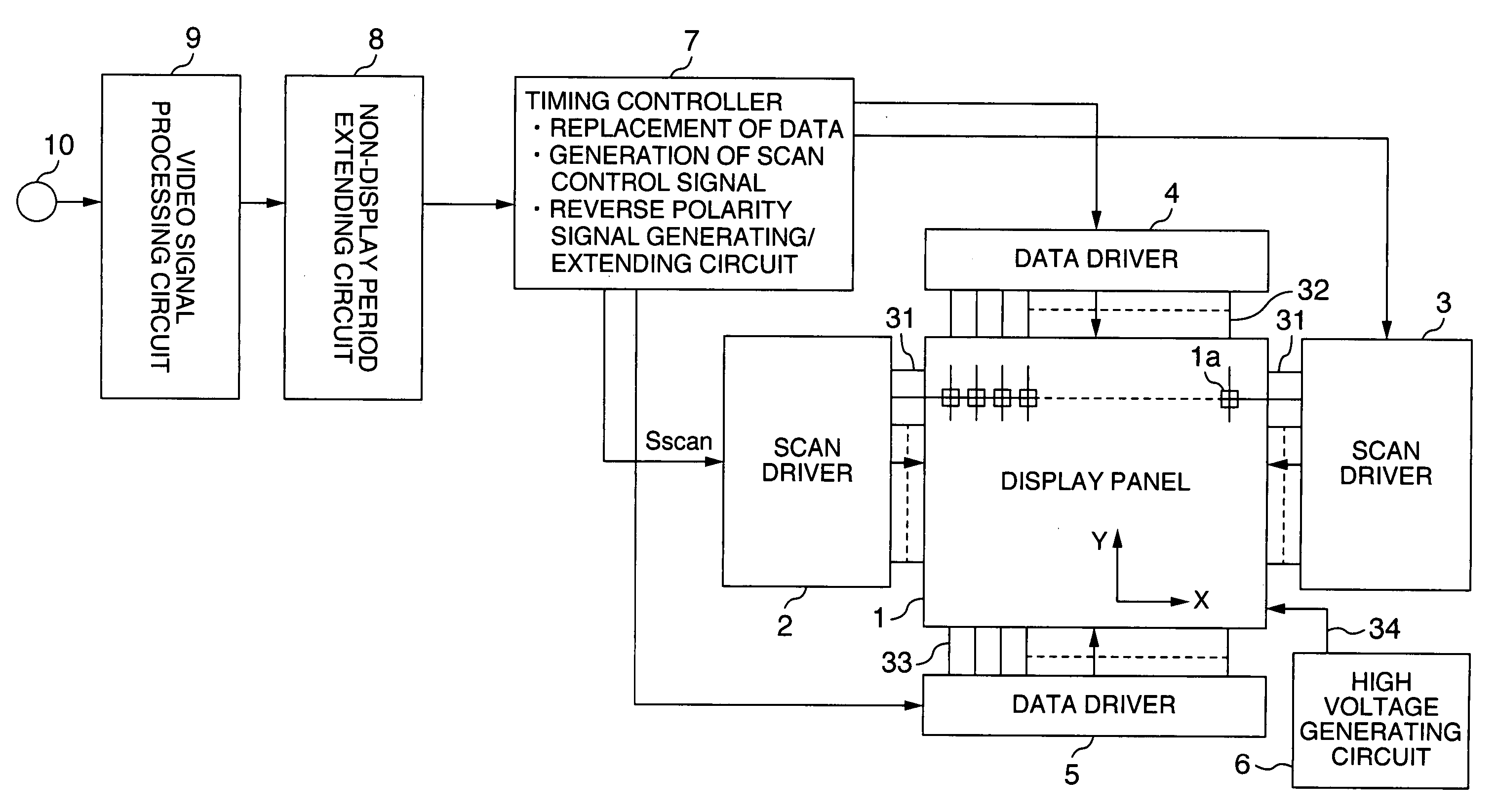
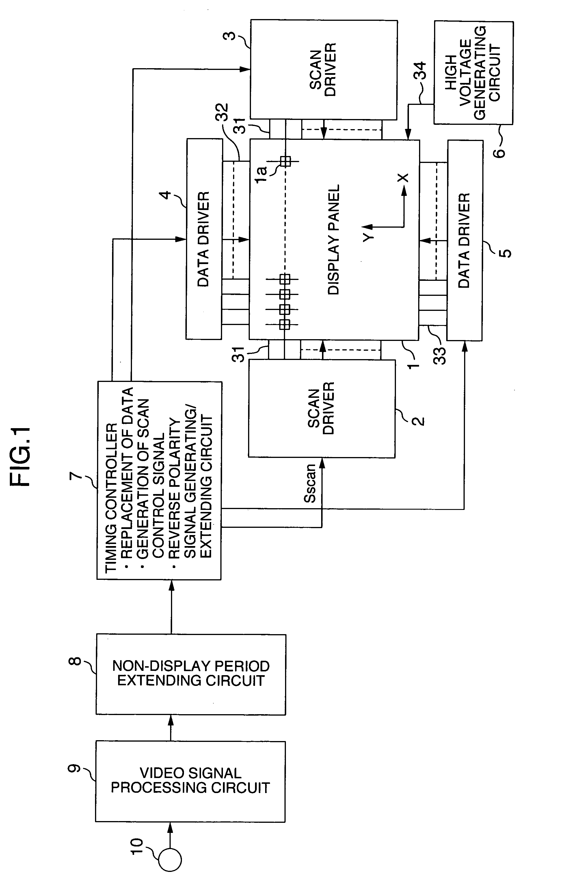
[0022]FIG. 1 is a block diagram showing the first embodiment of a display apparatus according to the invention. The embodiment is characterized by having: a non-display period extending circuit 8 for extending a non-display period; and a timing controller 7 having a reverse polarity signal generating function and an extending function for extending a reverse polarity signal period of its reverse polarity signal.
[0023] As shown in FIG. 1, the display apparatus of the embodiment comprises: a display panel 1 in which a plurality of thin-film type electron-emitter elements are placed in a matrix form; scan drivers (scan line drive circuits) 2 and 3 and data drivers (data line drive circuits) 4 and 5 for driving the display panel 1; a high voltage generating circuit 6 for generating a high acceleration voltage which is applied to the display panel 1; a video signal processing circuit 9 for executing a predetermined signal process to a video signal which is inputted from a video input te...
embodiment 2
[0052] The second embodiment to extend the vertical non-display period of the video image will now be described with reference to FIGS. 5A and 5B. A block diagram of a display apparatus according to the second embodiment is substantially the same as that of FIG. 1. Also in the embodiment, component elements having common functions are designated by the same reference numerals and their explanation is omitted.
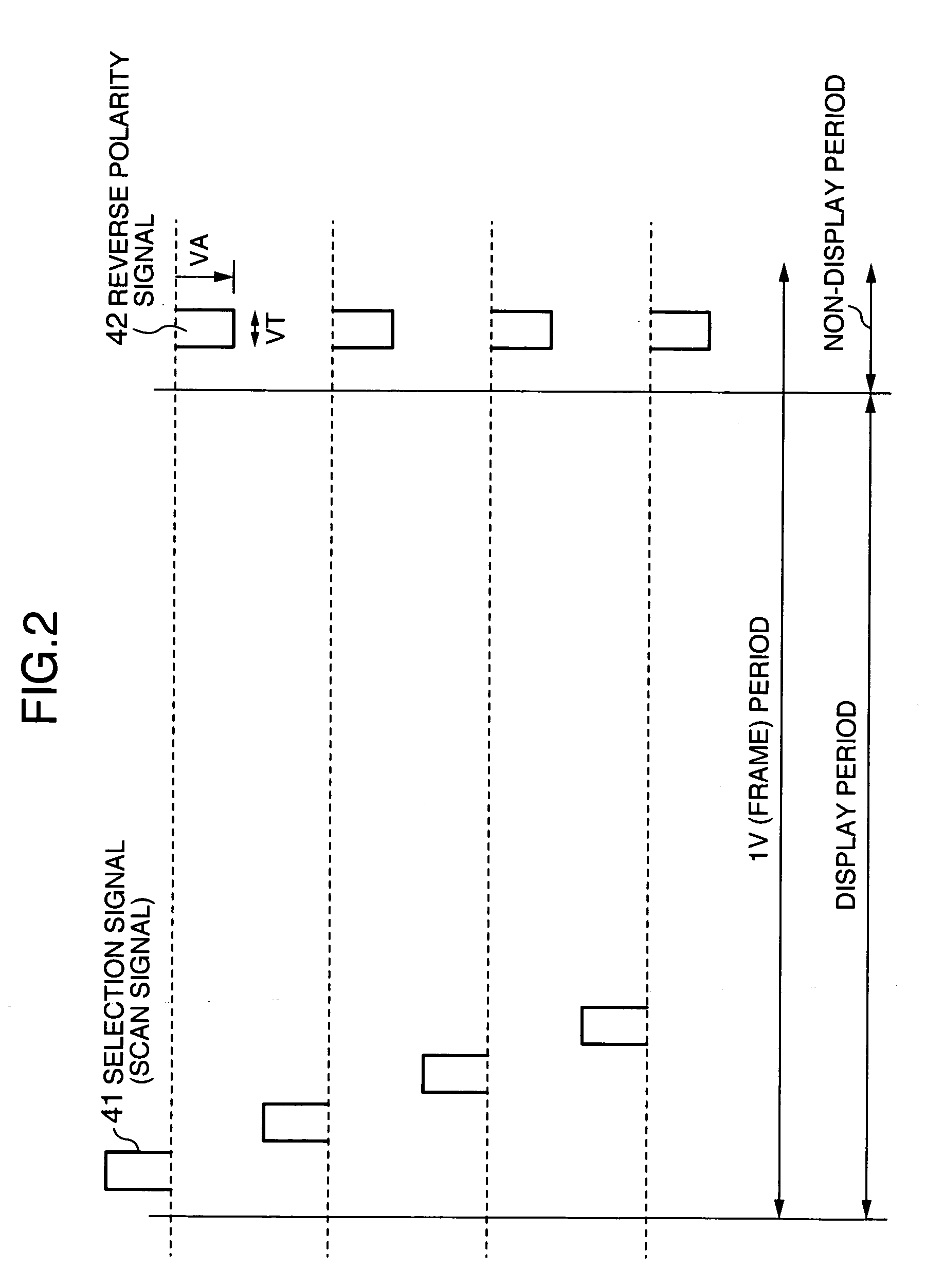
[0053]FIG. 5A shows conventional video timing. FIG. 5B shows video timing according to the embodiment. It is assumed that, in the conventional technique and the embodiment, the 1V period (1 frame period) of the video image is not changed. In a manner similar to FIG. 4A, FIG. 5A is illustrated to show a difference from the embodiment and its explanation is omitted.
[0054] Unlike the first embodiment in which the number of dots in the 1H non-display period is reduced, according to the embodiment, as shown in FIG. 5B, the number of dots (L) of the display period of 1H and the numb...
embodiment 3
[0057] The third embodiment to extend the vertical non-display period of the video image will now be described with reference to FIGS. 6A and 6B. A block diagram of a display apparatus according to the embodiment is substantially the same as that of FIG. 1. Also in the embodiment, component elements having common functions are designated by the same reference numerals and their explanation is omitted.
[0058]FIG. 6A shows conventional video timing. FIG. 6B shows video timing according to the embodiment. It is assumed that, in the conventional technique and the embodiment, the 1V period (1 frame period) of the video image is not changed. In a manner similar to FIG. 4A, FIG. 6A is illustrated to show a difference from the embodiment and its explanation is omitted.
[0059] The third embodiment relates to a combination of the first and second embodiments. As shown in FIG. 6B, the 1-dot period is shortened and the number of dots (HB) of the non-display period (horizontal non-display period...
PUM
 Abstract
Description
Claims
Application Information