Backlight, a lens for a backlight, and a backlight assembly having the same

a technology of backlight and lens, which is applied in the field of backlights, can solve the problems of increasing the number of led elements disposed on the plane, the light emitted from the led element is not uniformly distributed over a wide area, and the manufacturing cost of the backligh

Active Publication Date: 2008-05-01
SAMSUNG DISPLAY CO LTD
View PDF6 Cites 206 Cited by
  • Summary
  • Abstract
  • Description
  • Claims
  • Application Information

AI Technical Summary

Benefits of technology

[0011]The curvature of the convex surface of the inner surface area is greater than the curvature of the convex surface of the outer surface area, and the curvature of the concave surface of the inner surface area is smaller than the curvature of the concave surface of the outer surface area.
[0012]The convex surface of the outer surface area is disposed in a central area of the light transmissive body and has a first curvature; the concave surface of the outer surface area has a second curvature and extends from an end of the convex surface of the outer surface area to an edge of the light transmissive body; the convex surface of the inner surface area is disposed in the central area of the light transmissive body and has a third curvature greater than the first curvature; and the concave surface of the inner surface area has a fourth curvature smaller than the second curvature and extends from an end of the convex surface of the inner surface area to the edge of the light transmissive body. The third curvature is about 1.5 times to about 10 times greater than the first curvature and the second curvature is about 1.5 times to about 5 times greater than the fourth curvature.

Problems solved by technology

In other words, an illuminance distribution on a horizontal plane spaced a predetermined distance apart from the LED element exhibits a substantial Gaussian distribution, thus the light emitted from the LED element is not uniformly distributed over a wide area.
However, this increases the number of LED elements disposed on a plane and, in turn, the manufacturing cost of the backlight.
Thus, for example, when some of the LED elements in the backlight are driven to locally supply light to an area of a liquid crystal display device, the light spreads to the overhead and peripheral areas of the LED element, thereby causing a light leakage phenomenon.

Method used


Image

  • Backlight, a lens for a backlight, and a backlight assembly having the same
  • Backlight, a lens for a backlight, and a backlight assembly having the same
  • Backlight, a lens for a backlight, and a backlight assembly having the same

Examples


Embodiment Construction

[0041]The present invention will be described more fully hereinafter with reference to the accompanying drawings, in which exemplary embodiments of the invention are shown. This invention may, however, be embodied in many different forms and should not be construed as being limited to the embodiments set forth herein.

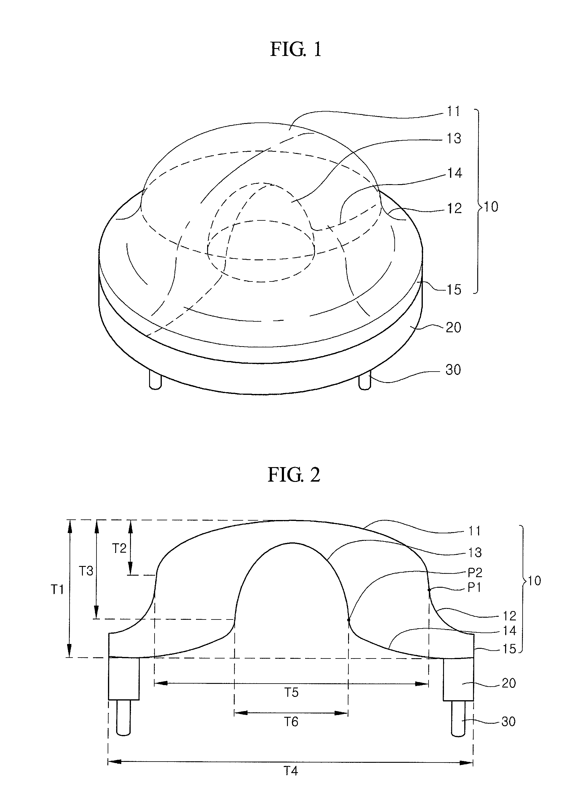
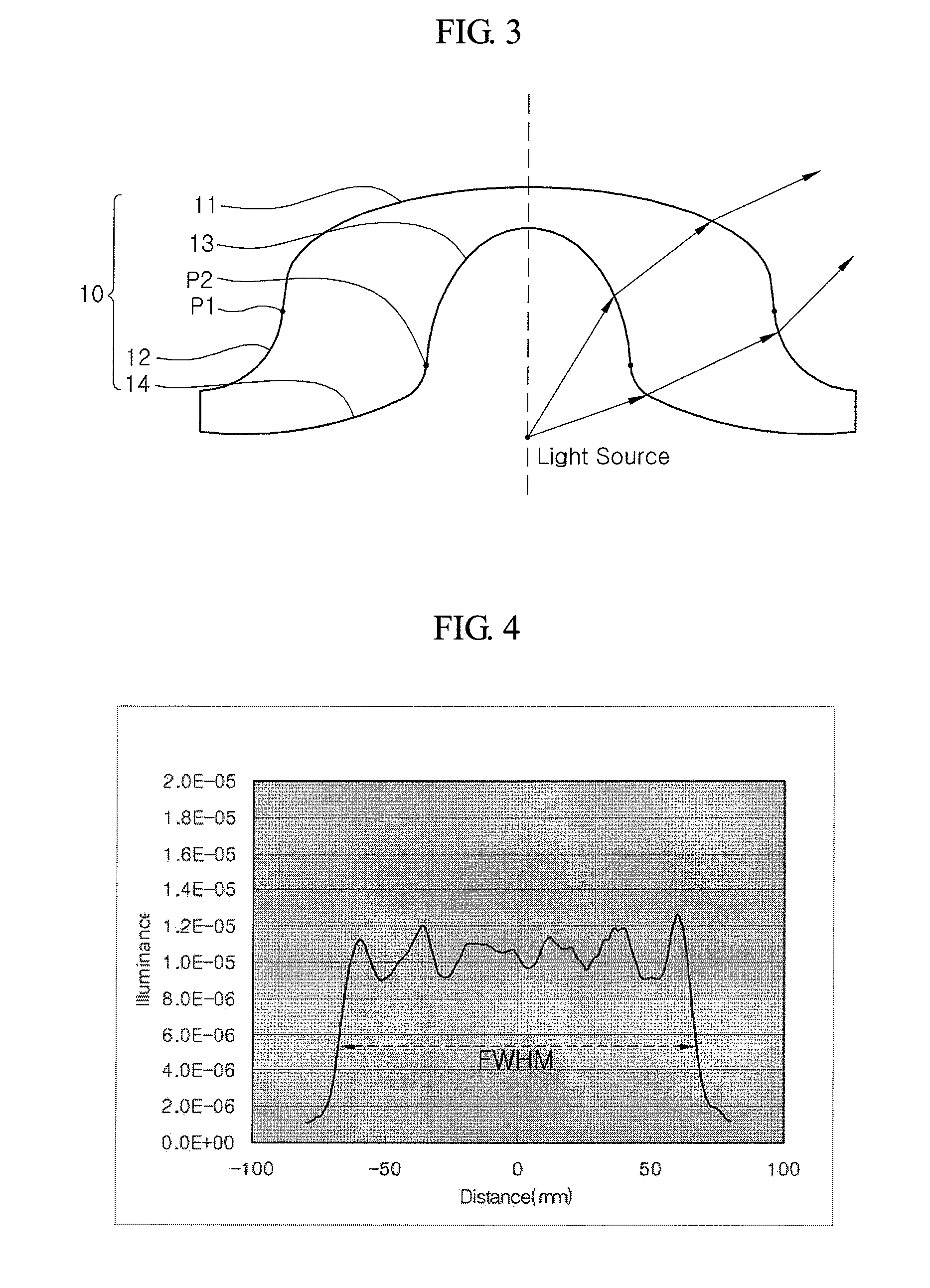
[0042]FIG. 1 is a perspective view of a lens for a backlight according to an exemplary embodiment of the present invention, and FIG. 2 is a sectional view illustrating the lens of FIG. 1. FIG. 3 is a sectional view illustrating a light emitting characteristic of the lens of FIG. 1. FIG. 4 is a simulation result graph illustrating an illuminance distribution of the lens of FIG. 1.

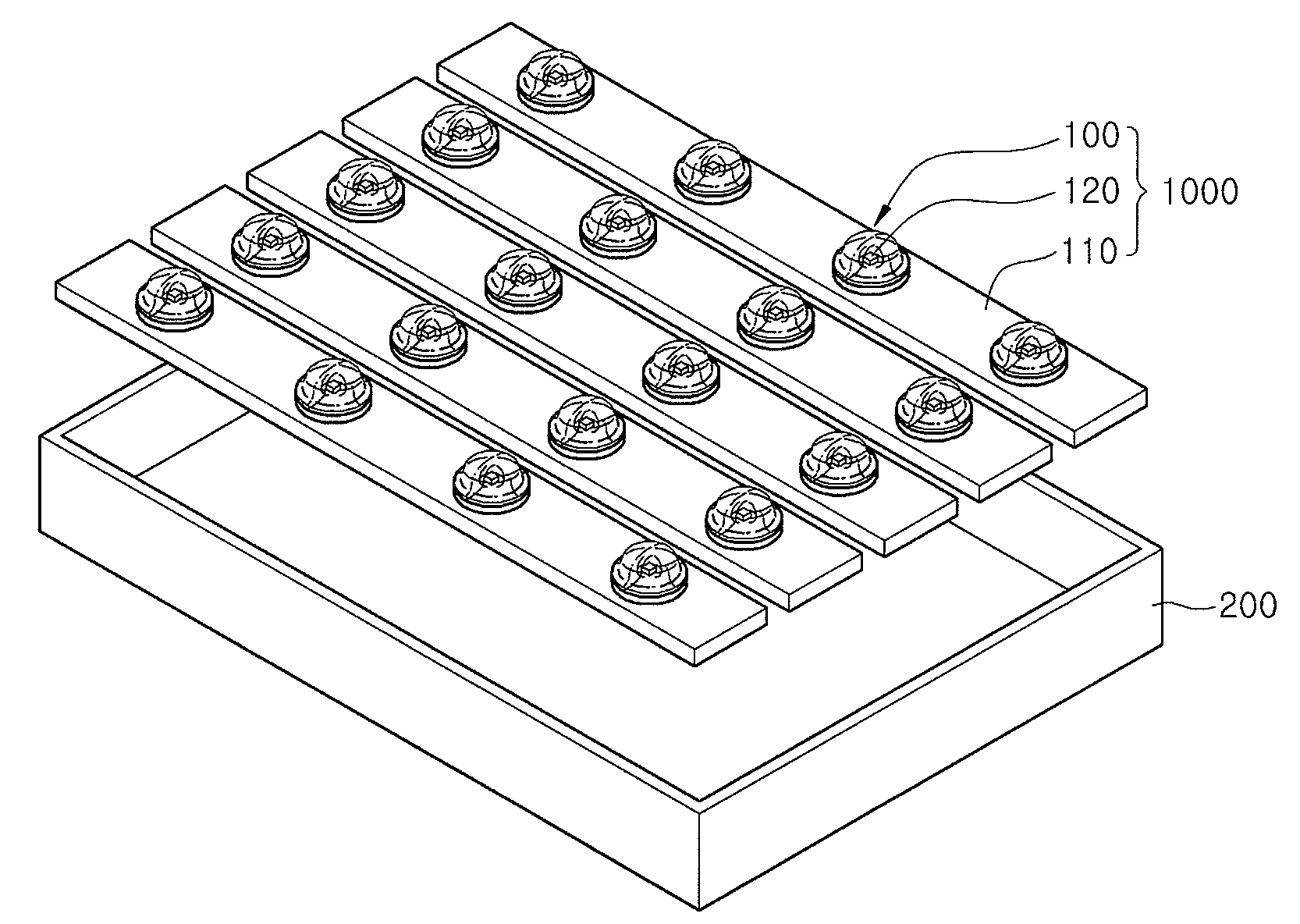
[0043]Referring to FIGS. 1 and 2, the lens for a backlight according to this exemplary embodiment includes a light transmissive body 10 having inner and outer curved surfaces.

[0044]In the body 10, the outer curved surface includes a convex surface 11 and a concave surface 12, and the inner curve...


PUM

PropertyMeasurementUnit
radiusaaaaaaaaaa
radiusaaaaaaaaaa
radiusaaaaaaaaaa

Abstract

A lens for a backlight, including: a light transmissive body including outer and inner surface areas, the outer surface area having a convex surface and a concave surface, the inner surface area having a convex surface and a concave surface, wherein the convex surface of the outer surface area has a curvature different from a curvature of the convex surface of the inner surface area and the concave surface of the outer surface area has a curvature different from a curvature of the concave surface of the inner surface area.

Description

CROSS-REFERENCE TO RELATED PATENT APPLICATION[0001]This application claims priority to Korean Patent Application No. 2006-0106462, filed on Oct. 31, 2006, in the Korean Intellectual Property Office, the disclosure of which is incorporated by reference herein in its entirety.BACKGROUND OF THE INVENTION[0002]1. Technical Field[0003]The present invention relates backlights, and more particularly, to a lens for a backlight capable of uniform illuminance distribution, a backlight capable of preventing a light leakage phenomenon, and a backlight assembly having the same.[0004]2. Discussion of the Related Art[0005]A liquid crystal display device displays an image by using a separate light source. In other words, the liquid crystal display device does not emit light by itself. Therefore, the liquid crystal display device includes a lighting unit such as a backlight.[0006]A cold cathode fluorescent lamp (CCFL) has been used as a conventional light source for the backlight. In some applicatio...

Claims


Application Information

Patent Timeline
Patent Type & Authority Applications(United States)
IPC IPC(8): F21V23/02F21S8/00G02F1/1335F21V11/00
CPCF21V5/04G02B3/005G02B3/0056F21Y2101/02G02F1/133606G02F2001/133607G02B3/04F21Y2115/10G02B19/0009G02B19/0061G02F1/133607G02F1/1335
Inventor HWANG, SEONG YONGPARK, SE KICHOI, JIN SUNGKIM, JIN SOO
Owner SAMSUNG DISPLAY CO LTD
Why Eureka
Try Eureka