Implants and delivery system for treating defects in articulating surfaces

a technology of articulating surface and implants, which is applied in the field of implants and delivery systems for treating cartilage and bone defects, can solve the problems of complex shape of tissue surface in the defect area, and achieve the effect of improving the quality of cartilage and bone repair

Inactive Publication Date: 2006-08-10
OSTEOBIOLOGICS
View PDF31 Cites 164 Cited by
  • Summary
  • Abstract
  • Description
  • Claims
  • Application Information

AI Technical Summary

Benefits of technology

[0023] A cylindrical inner shaft, also having proximal and distal ends, is disposed within the internal bore in the outer shaft, wherein the proximal end of the inner shaft is suitable for insertion into a defect. By “suitable for insertion into a defect” it is meant that the proximal end of the inner shaft has a size and shape allowing it to fit within a bone and / or cartilage defect without distorting the defect or damaging the tissue layers. In the present invention, the distal end of the inner shaft has a size and shape similar to the size and shape of the proximal surface of the implant. The shaped surface of the inner shaft helps to keep the implant in proper orientation. The inner shaft has a diameter that also allows it to be slidably engaged with the outer shaft. “Slidably engaged” means the inner shaft can slide within the bore in the outer shaft. The inner shaft may be solid or have a cannula through its center. The inner shaft and outer shaft are of the same effective length. The inner shaft and the outer shaft are of the same effective length when the proximal end of the outer shaft and the flat end of the inner shaft are placed in contact with a flat surface and the shaped distal ends of the inner and outer shafts are aligned. When the proximal ends of the inner and outer shafts are aligned, the shape on the distal ends of the inner and outer shafts match. Because one end of the inner shaft is contoured, the contoured portions of inner shaft may be longer than the center measuring site.
[0025] In addition, the delivery device may be designed to limit rotation of the inner shaft within the outer shaft. For example, one of a key or keyway may be located on the inner shaft, with the other of key or keyway located on the outer shaft. The interlocking of the key and keyway limits or prevents rotation of the inner shaft within the outer shaft.
[0029] While the device can be constructed of any materials, including, but not limited to, medical grade plastic or metal, it is preferred that plastic is used to prevent scratching the bone or cartilage surface. In a further embodiment, a series of thin concentric slots cut into the outer surface of the outer shaft provide a gripping surface for easier handling of the device.
[0031] A further embodiment of this invention includes tapered leaves in the distal end of the outer shaft. Longitudinal slots are cut in the distal end of the outer shaft, creating opposing leaves. The leaves are the sections of the outer shaft between the longitudinal slots. These leaves can be made to taper slightly inward, creating slight compression on the implant to prevent undesired movement of the implant within the device.
[0032] A further embodiment of this invention includes a snap-bead feature on the distal end of the outer shaft for attaching items to the device. The snap-bead feature comprises an annular groove around the distal end of the outer shaft. An attachable item has one or more small beads or a rim that fits into this groove. One such attachable item is a temporary cap that fits over the distal end of the outer shaft to prevent accidental removal of the implant from the device.

Problems solved by technology

Defects may occur such that the shape of the tissue surface in the defect area is complex.

Method used


Image

  • Implants and delivery system for treating defects in articulating surfaces
  • Implants and delivery system for treating defects in articulating surfaces
  • Implants and delivery system for treating defects in articulating surfaces

Examples


example

Dual-Phase Implant Plug

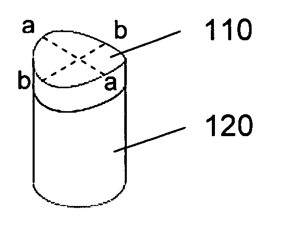
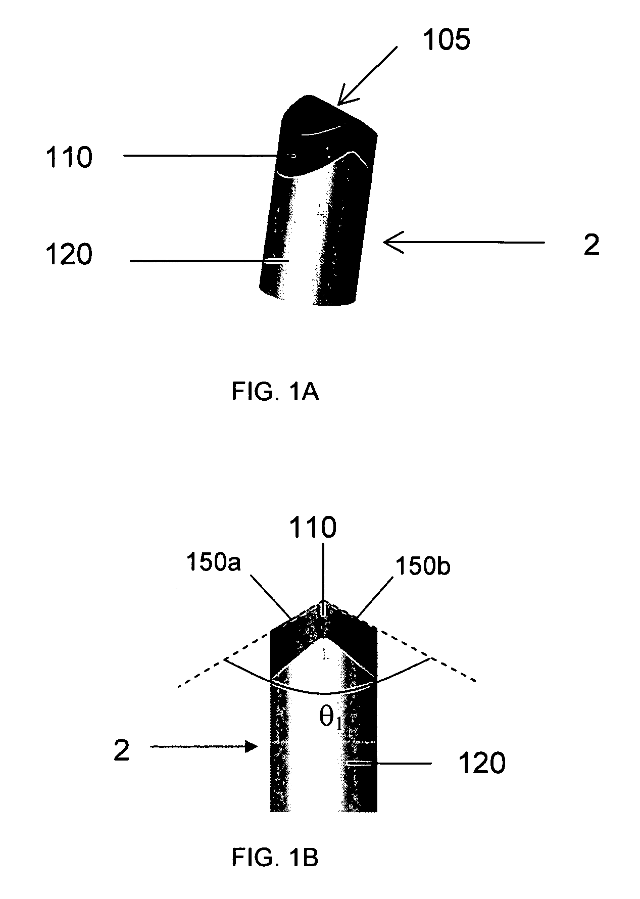
[0132] The dual-phase implant plug has a proximal layer designed to have properties similar to that of cartilage and a distal layer designed to have properties similar to that of bone. Table 3 lists an exemplary composition for the bone phase, while Table 4 lists an exemplary composition for the cartilage phase. The PGA fibers listed in the tables are of poly-glycolic acid. Table 5 lists exemplary physical properties of bone and cartilage phases having the compositions listed in Tables 3 and 4.

TABLE 3Bone phase:ComponentQuantity (vol %)Poly-lactic acid54%PGA Fibers10%Calcium Phosphate35%Surfactant 1%

[0133]

TABLE 4Cartilage PhaseComponentQuantity (vol %)Poly-lactic-co-93% glycolide, 75 / 25PGA Fibers6%Surfactant1%

[0134]

TABLE 5Physical PropertiesBone PhaseCartilage PhasePorosity70%80%Pore size100-600μm80-250μmStrength25MPa1.5MPaStiffness150MPa25MPaPhase thickness12.5mm2.5mm


PUM

PropertyMeasurementUnit
angleaaaaaaaaaa
angleaaaaaaaaaa
angleaaaaaaaaaa

Abstract

The invention provides implant plugs having a complex clinically acceptable proximal surface. The invention also provides multi-phase implant plugs which have a nonplanar proximal surface. Suitable implant proximal surface shapes include, but are not limited to, concave surfaces, convex surfaces, faceted domes and angled surfaces formed by the convergence of two facets. The implants of the invention are suitable for repair of tissue defects in articulating surfaces. The invention also provides delivery devices and methods for delivering the implants of the invention. The invention also provides methods for creating defects suitable for use with the implants of the invention.

Description

CROSS-REFERENCE TO RELATED APPLICATIONS [0001] This application claims the benefit of U.S. Provisional Application 60 / 632,050, filed Nov. 30, 2004, and is a continuation-in-part of U.S. application Ser. No. 11 / 052,626, filed Feb. 7, 2005, which claims the benefit of U.S. Provisional Application 60 / 542,640 filed on Feb. 5, 2004, all of which are incorporated by reference to the extent not inconsistent with the disclosure herein.BACKGROUND OF THE INVENTION [0002] This invention relates to implants, devices, and methods for performing repairs of cartilage and bone defects, where the defects are located on nonplanar or complex surfaces. [0003] It is well known in the art that implants can be inserted into damaged bone or cartilage layers to treat injuries to those tissue layers. One type of procedure involves inserting plugs of healthy bone or cartilage that are harvested from a healthy area of the patient's body and transplanted into the defect, as disclosed in U.S. Pat. Nos. 5,152,763...

Claims


Application Information

Patent Timeline
Patent Type & Authority Applications(United States)
IPC IPC(8): A61F2/30A61B17/17
CPCA61B17/1604A61B17/1615A61B17/1635A61B17/1637A61B17/17A61B17/1767A61B2019/462A61F2/28A61F2/30756A61F2/3094A61F2/30965A61F2/3877A61F2/4601A61F2/461A61F2/4618A61F2/4657A61F2002/2817A61F2002/2839A61F2002/30004A61F2002/30011A61F2002/30014A61F2002/30057A61F2002/30062A61F2002/30224A61F2002/30301A61F2002/30324A61F2002/30616A61F2002/30677A61F2002/30971A61F2002/4635A61F2002/4648A61F2002/4649A61F2002/4662A61F2210/0004A61F2230/0069A61F2230/0095A61F2250/0014A61F2250/0018A61F2250/0023A61F2250/0036A61F2310/00293A61F2002/4627A61B2090/062
Inventor DINGER, FRED B. IIILEATHERBURY, NEIL C.WRANA, JEFFREY S.PAK, JOHNNIEDERAUER, GABRIELE G.
Owner OSTEOBIOLOGICS
Why Eureka
Try Eureka