High flexion articular insert

a technology of articular inserts and knees, applied in the field of knee prostheses, can solve the problems of unwanted movement of the femoral component on the tibial component, inability to fully bend the knee, and difficulty in daily living, etc., and achieve the effect of minimizing impingemen

Inactive Publication Date: 2005-06-30
SMITH & NEPHEW INC
View PDF30 Cites 163 Cited by
  • Summary
  • Abstract
  • Description
  • Claims
  • Application Information

AI Technical Summary

Benefits of technology

[0018] According to certain aspects and embodiments of the invention, there is provided a knee prosthesis having a femoral component adapted to fit on a distal end of a femur, the femoral component including a lateral condylar structure and a medial condylar structure and an intermediate structure configured to cooperate with the femoral component. The intermediate structure includes at least one surface for contacting the femoral component, a transition of a sagittal curvature of the contact surface from a concave surface into a convex surface, the transition occurring at a contact point between the femoral component and the intermediate structure when the knee prosthesis is flexed at approximately 120° to 140°, and a post adapted to provide posterior support to the femoral component, the post being adapted to minimize impingement on a patellar component when the knee is flexed approximately 130° or greater.

Problems solved by technology

This may be due to either old age, congenital deformity, or damage due to trauma.
In either case, when the surface of the joint is worn away, the activities of daily living can become very difficult.
In many cases, however, despite the above non-surgical treatments, functional limitations persist.
Another problem encountered by TKR patients is unwanted movement of the femoral component on the tibial component.
A tight posterior cruciate ligament may cause the knee to move in an unnatural motion.
This can lead to excessive polyethylene wear.
In conforming knee designs, this can limit range of motion because more implant material is located on the posterior edge of the insert.
Thus, there is a need for an insert that provides sufficient posterior support and reduces posterior conformity.

Method used


Image

  • High flexion articular insert
  • High flexion articular insert
  • High flexion articular insert

Examples


Embodiment Construction

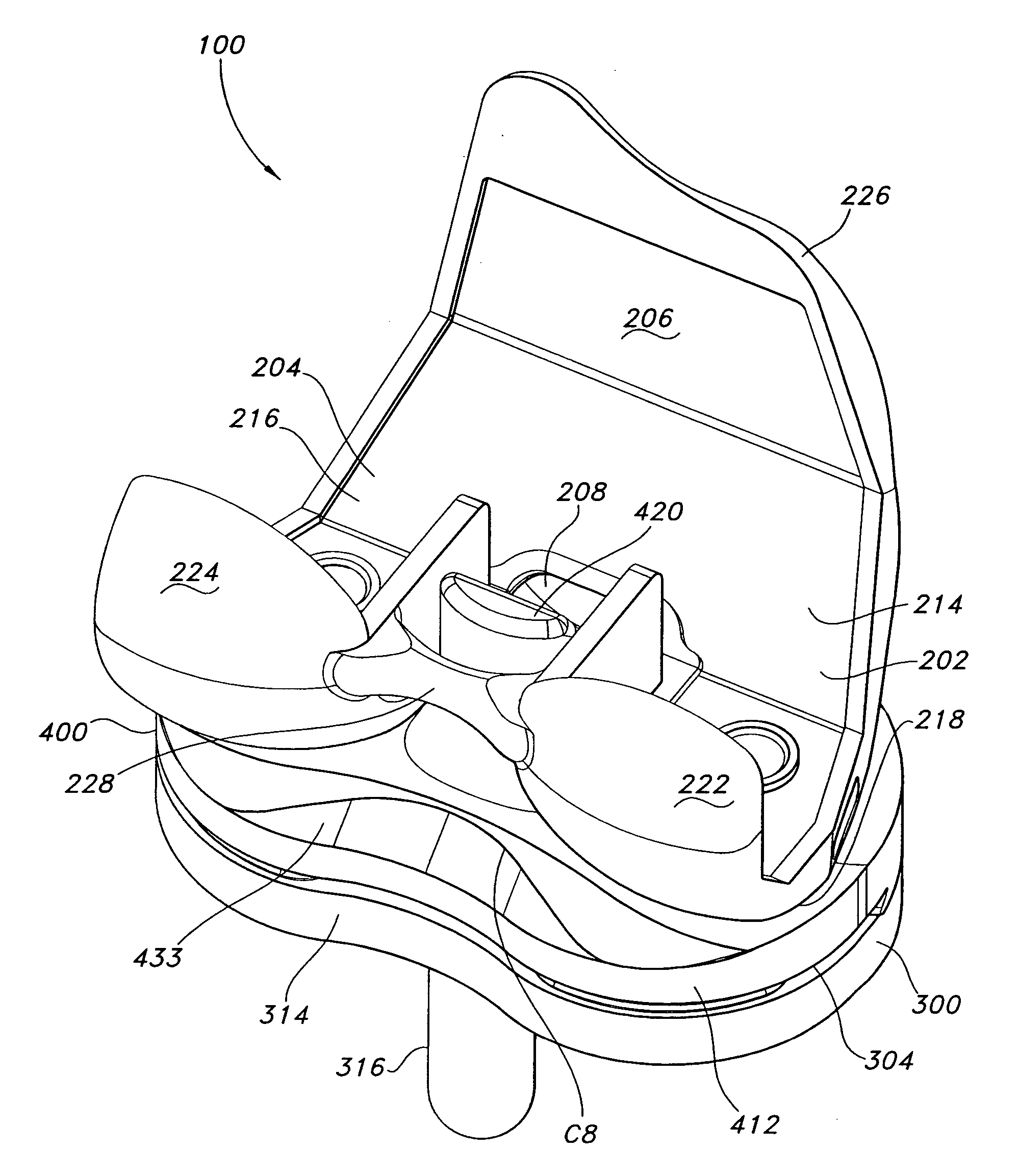
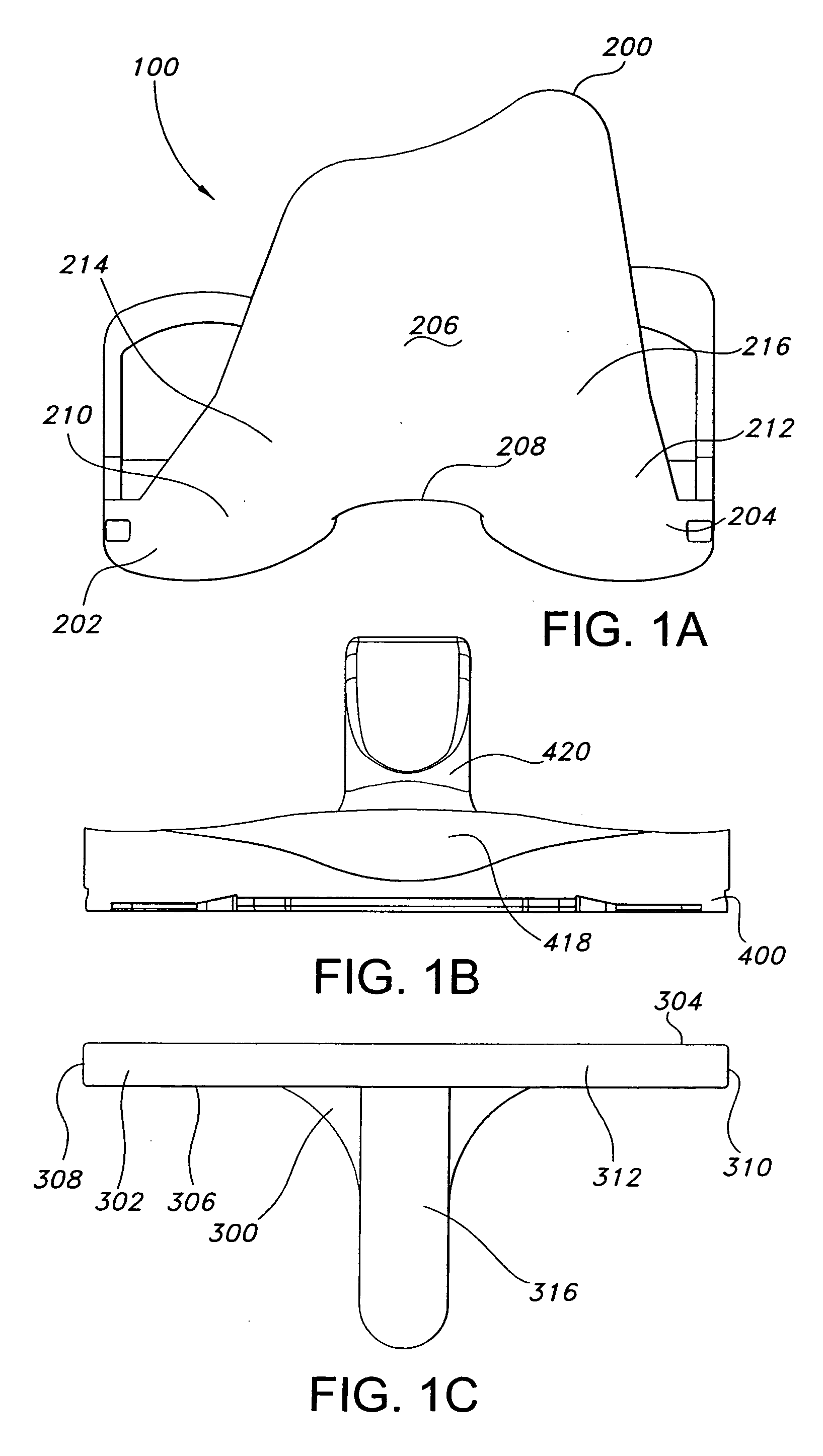
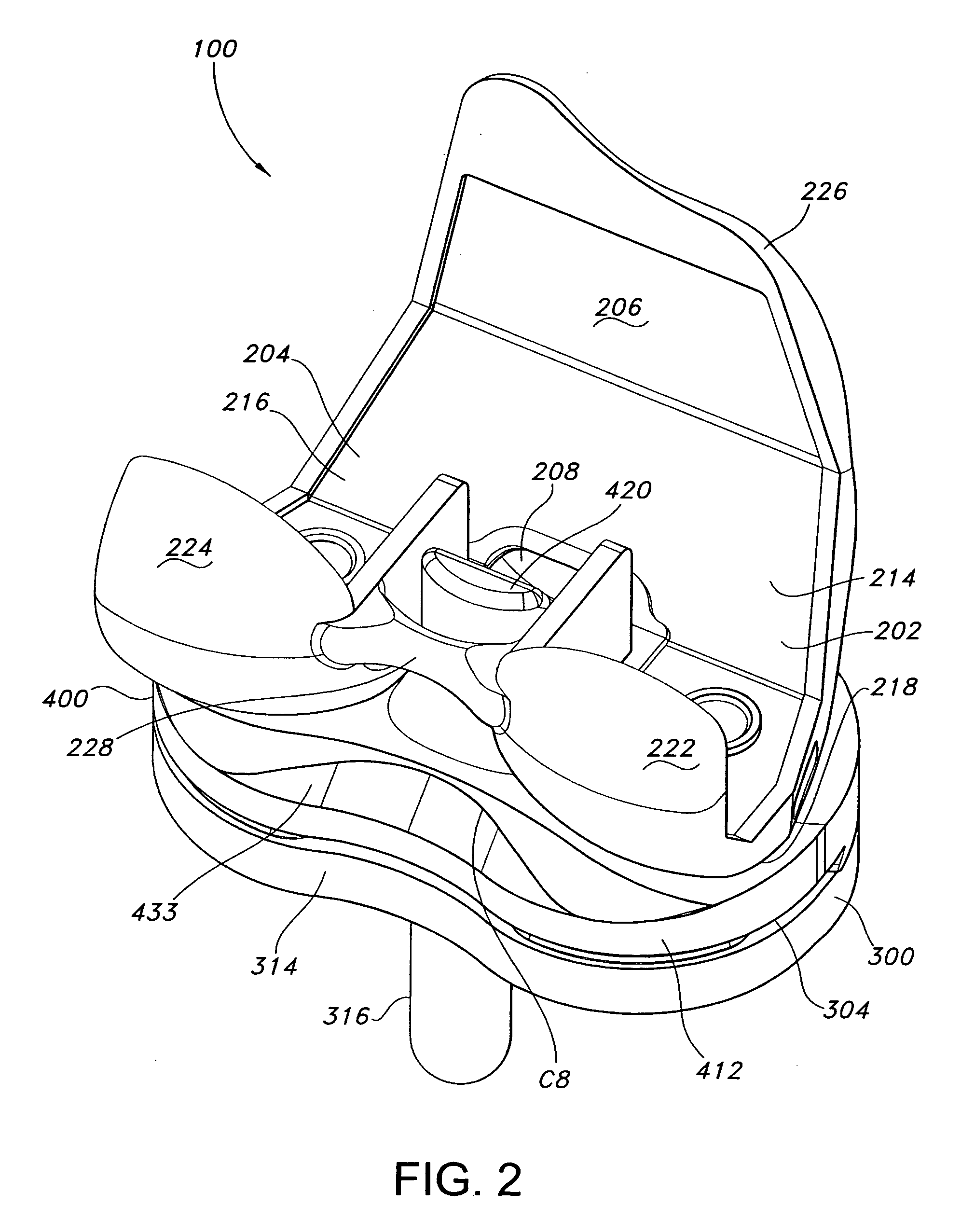
[0032] Various embodiments of the invention provide improved knee prostheses for replacing at least a portion of a knee joint between the distal end of a femur and the proximal end of a tibia.

[0033] As used herein, the following directional definitions apply. Anterior and posterior mean toward the front or toward the back of the body, respectively. Proximal means nearer to a point of reference, as opposed to distal which means farther from a point of reference. For example, the distal femur is part of the knee joint, while the proximal femur is part of the hip joint. Medial means nearer to the middle or center of the body. Lateral means farther from the middle or center of the body. Thus, when referring to the knee, medial would mean the side of the knee that is closest to the other knee and lateral would mean the side of the knee that is farthest from the other knee.

[0034] Knee prostheses according to certain embodiments of the invention advantageously remove material from the po...


PUM


Abstract

A knee prosthesis is provided that allows for increased flexion. The knee prosthesis includes (a) a femoral component adapted to fit on a distal end of the femur which includes a lateral condylar structure and a medial condylar structure and (b) an intermediate structure configured to cooperate with a femoral component of a knee prosthesis. The intermediate structure includes at least one surface for contacting the femoral component and a transition of a sagittal curvature of the at least one contact surface from a concave surface into a convex surface at the contact interface of the femoral component and the intermediate structure when the knee is flexed at approximately 120° to 140°. The knee prosthesis minimizes impingement on the femoral posterior cortex in deep flexion, increases the dislocation safety factor and allows for easier reengagement of the articular surface should the femoral component externally rotate off of the tibial plateau.

Description

CROSS REFERENCE TO RELATED APPLICATIONS [0001] This application claims priority to U.S. Application Ser. No. 60 / 512,457, filed on Oct. 17, 2003.BACKGROUND OF THE INVENTION [0002] 1. Field of the Invention [0003] The invention relates generally to knee prostheses and, more specifically, to knee prostheses which include the use of posterior stabilized inserts and have an extended range of flexion. [0004] 2. General Background of the Invention [0005] Arthritis of the knee is a disease in which the surfaces of the knee gradually “wear out.” Osteoarthritis, characterized by chronic degeneration of the cartilage of the joints, is the most common form of arthritis. This may be due to either old age, congenital deformity, or damage due to trauma. Osteoarthritis, characterized by chronic degeneration of the cartilage of the joints, is the most common form of arthritis. Systemic arthritis, such as rheumatoid arthritis, or gout affects the synovium (the membrane tissue in the joint that normal...

Claims


Application Information

Patent Timeline
Patent Type & Authority Applications(United States)
IPC IPC(8): A61F2/00A61F2/30A61F2/38A61F2/46
CPCA61F2/30942A61F2/3886A61F2002/30133A61F2002/30388A61F2002/30604A61F2002/30616A61F2310/00029A61F2002/30878A61F2002/30884A61F2002/30957A61F2002/4631A61F2220/0025A61F2230/0015A61F2002/30822A61F2002/30387
Inventor CARSON, CHRISTOPHER P.
Owner SMITH & NEPHEW INC
Why Eureka
Try Eureka