Infrared suppression system

a suppression system and infrared technology, applied in the direction of efficient propulsion technologies, machines/engines, transportation and packaging, etc., can solve the problems of lowering the aircraft ir signature, limited ir suppression system, and limited adaptation to relatively small rotary wing aircraft or retrofitting to aircraft which require maintaining current packaging constraints, etc., to suppress the ir energy of a high temperature engine exhaust flow

Inactive Publication Date: 2008-10-09
SIKORSKY AIRCRAFT CORP
View PDF9 Cites 1 Cited by
  • Summary
  • Abstract
  • Description
  • Claims
  • Application Information

AI Technical Summary

Benefits of technology

[0008]Accordingly, it is desirable to provide an infrared suppression system which reduces the overall IR signature of the aircraft, is compact in design, masks the IR energy emitted / radiated from the gas turbine engine for a given viewing / azimuth angle, and minimizes impingement of engine exhaust onto adjacent aircraft structure while maintaining aircraft performance characteristics.
[0006]Current suppression systems for rotary wing aircraft are primarily designed to provide significant IR signature reduction during a hover flight profile. Generally, current suppressor systems operate by mixing the high temperature exhaust flow with cool airflow supplied by a mixing duct which communicates with an engine exhaust duct. The mixing of large amounts of ambient air with the engine exhaust may significantly reduce the overall gas temperature prior to discharging the engine exhaust overboard, thereby lowering the aircraft IR signature. To achieve significant reductions in temperature, however, a relatively significant volume of ambient air must be mixed with the high temperature exhaust flow. This requires relatively large intakes and a final exhaust stage which provides a flow area capacity for both the engine exhaust flow volume and the mixed in additional ambient airflow volume. Another disadvantage of such an IR suppressor system is limited by the packaging space restrictions. That is, the elongate mixing areas downstream of the engine need to be of a relatively significant length to provide ample mixing and flow area. Adaptation to relatively small rotary wing aircraft or retrofitting to aircraft which require maintaining current packaging constraints is therefore limited.
[0008]Accordingly, it is desirable to provide an infrared suppression system which reduces the overall IR signature of the aircraft, is compact in design, masks the IR energy emitted / radiated from the gas turbine engine for a given viewing / azimuth angle, and minimizes impingement of engine exhaust onto adjacent aircraft structure while maintaining aircraft performance characteristics.
[0007]It is also desirable to minimize impingement of hot engine exhaust onto adjacent aircraft structure so that the generation of “hot spots” separate from the primary source associated with the nozzle / exhaust plume are avoided. Disadvantageously, the mixing operation may reduce the velocity of the exhaust flow such that the exhaust velocity may be too low to expel the exhaust far enough from the fuselage to avoid such “hot spots.” A further disadvantage is that if the exhaust gas does not have enough velocity to escape rotor downwash, the exhaust gas may be re-ingested into the engines which may reduce engine efficiency.
[0008]Accordingly, it is desirable to provide an infrared suppression system which reduces the overall IR signature of the aircraft, is compact in design, masks the IR energy emitted / radiated from the gas turbine engine for a given viewing / azimuth angle, and minimizes impingement of engine exhaust onto adjacent aircraft structure while maintaining aircraft performance characteristics.
[0008]Accordingly, it is desirable to provide an infrared suppression system which reduces the overall IR signature of the aircraft, is compact in design, masks the IR energy emitted / radiated from the gas turbine engine for a given viewing / azimuth angle, and minimizes impingement of engine exhaust onto adjacent aircraft structure while maintaining aircraft performance characteristics.

Problems solved by technology

With respect to the former, generally speaking, a heat-seeking missile obtains directional cues from the infrared energy generated by the engine exhaust such that the amount of infrared energy given off is one of the primary determining factors of a missile's accuracy, and consequently, lethality.
The mixing of large amounts of ambient air with the engine exhaust may significantly reduce the overall gas temperature prior to discharging the engine exhaust overboard, thereby lowering the aircraft IR signature.
Another disadvantage of such an IR suppressor system is limited by the packaging space restrictions.
Adaptation to relatively small rotary wing aircraft or retrofitting to aircraft which require maintaining current packaging constraints is therefore limited.
Disadvantageously, the mixing operation may reduce the velocity of the exhaust flow such that the exhaust velocity may be too low to expel the exhaust far enough from the fuselage to avoid such “hot spots.” A further disadvantage is that if the exhaust gas does not have enough velocity to escape rotor downwash, the exhaust gas may be re-ingested into the engines which may reduce engine efficiency.

Method used


Image

  • Infrared suppression system
  • Infrared suppression system
  • Infrared suppression system

Examples


Embodiment Construction

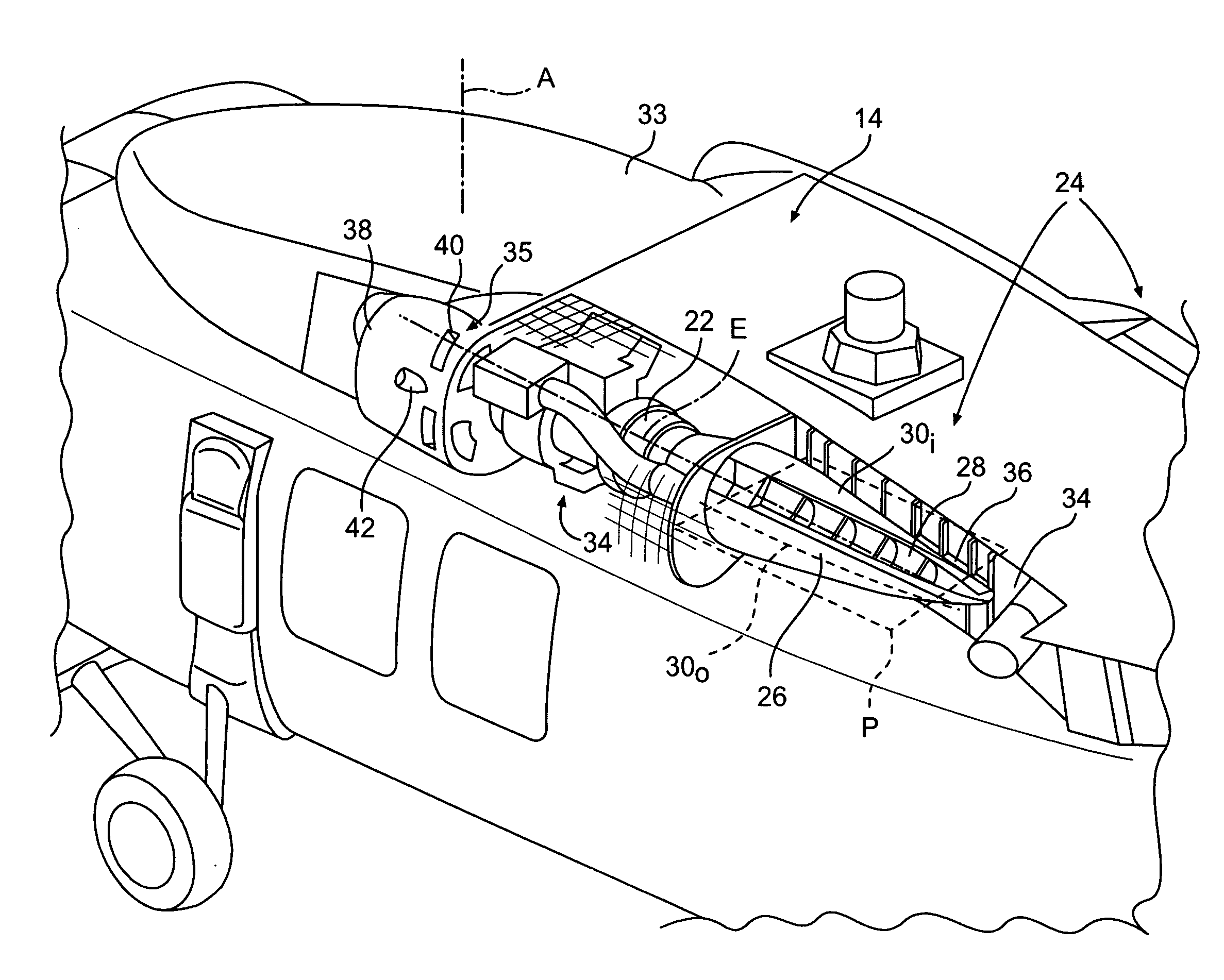
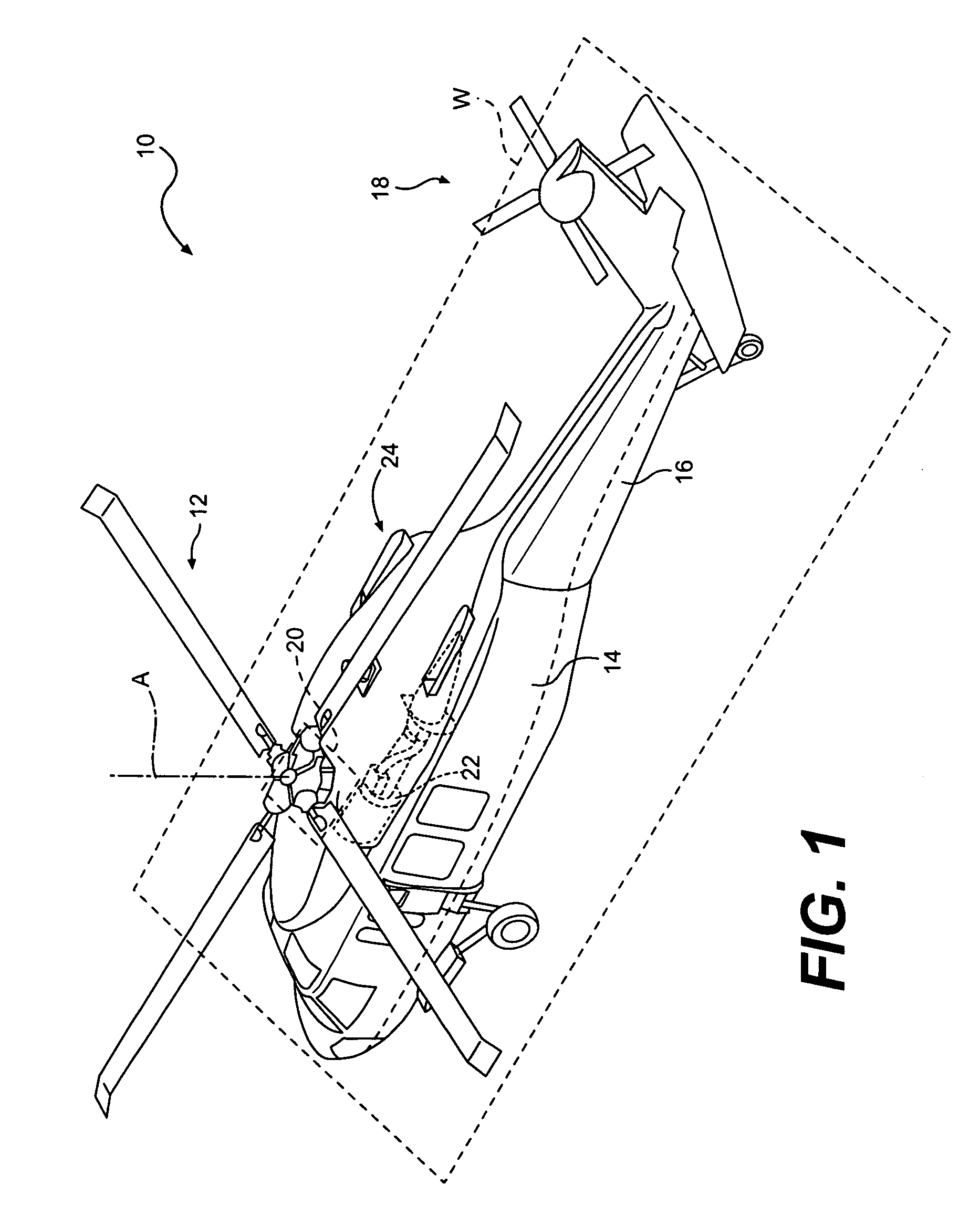
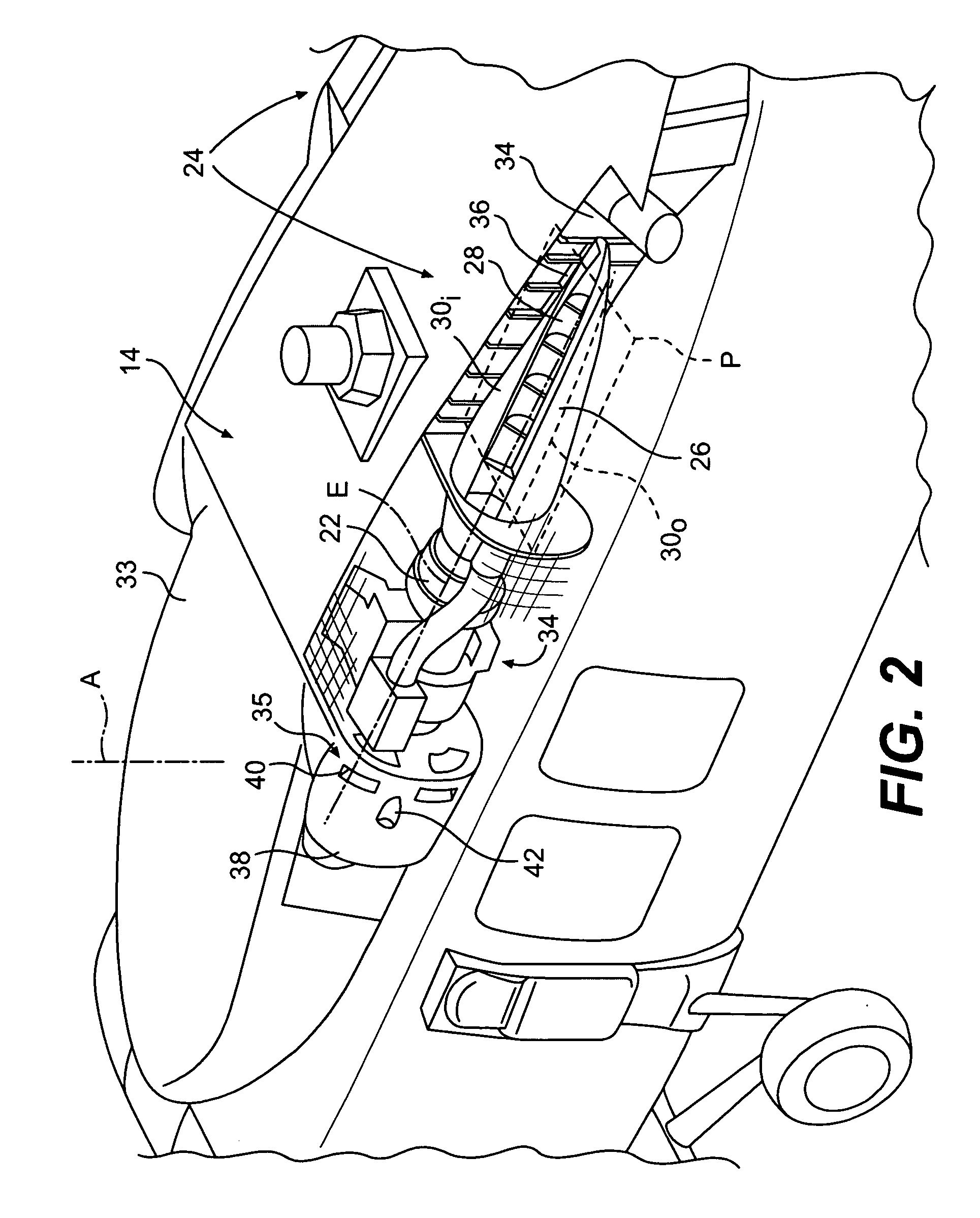
[0024]FIG. 1 schematically illustrates a rotary-wing aircraft 10 having a main rotor system 12. The aircraft 10 includes an airframe 14 having an extending tail 16 which mounts an anti-torque tail rotor system 18. The main rotor system 12 is driven about an axis of rotation A through a transmission (illustrated schematically at 20) by one or more gas turbine engines 22. Although a particular helicopter configuration is illustrated in the disclosed embodiment, other configurations and / or machines will also benefit from the present invention.

[0025]The rotary wing aircraft 10 also includes an InfraRed Suppression System (IRSS) 24 in communication with each gas turbine engine 22. The IRSS 24 suppresses the IR signature radiating from the high-temperature exhaust generated by the gas turbine engines 22. In the context used herein, “suppress” means that the IR signature emanating from the gas turbine engine 22 is reduced after passage through the IRSS 24 below that as expelled by the gas ...


PUM


Abstract

An InfraRed Suppression System (IRSS) vectors engine exhaust flow away from the exhaust manifold plane, the high aspect ratio exhaust duct defined as a ratio of a maximum nozzle length to a maximum nozzle width, the ratio greater than 2:1.

Description

[0001]This application is a continuation of U.S. application Ser. No. 11 / 194,229, which was filed on Aug. 1, 2005.BACKGROUND OF THE INVENTION[0002]The present invention relates to an infrared (IR) suppression system, and more particularly to a rotary wing aircraft having an upwardly directed infrared suppression system which (1) masks engine exhaust IR energy, which may signal ground threats during forward flight, and (2) minimizes engine exhaust impingement on adjacent aircraft structure to reduce the overall IR signature of the rotary wing aircraft.[0003]The exhaust ducting from a gas turbine engine is a source of high infrared energy which may be detected by heat seeking missiles and / or various forms of infrared imaging systems for targeting / tracking purposes. With respect to the former, generally speaking, a heat-seeking missile obtains directional cues from the infrared energy generated by the engine exhaust such that the amount of infrared energy given off is one of the primar...

Claims


Application Information

Patent Timeline
Patent Type & Authority Applications(United States)
IPC IPC(8): F02B27/04
CPCB64D33/04B64D2033/045F05D2210/42Y02T50/671F05D2220/329F02K1/825Y02T50/60
Inventor ZACK, DAVID W.CHAPKOVICH, JOHNFITTS, RICHARD A.
Owner SIKORSKY AIRCRAFT CORP
Why Eureka
Try Eureka