Thin, passive cooling system

a passive cooling and thin technology, applied in the direction of power cables, cables, semiconductor/solid-state device details, etc., can solve the problems of increasing power consumption and associated heat generation in these products, a considerable challenge to manage this thermal load, and a number of design constraints for portable devices such as laptop computers (notebook pcs), cellular telephones,

Active Publication Date: 2008-05-01
APPLE INC
View PDF6 Cites 43 Cited by
  • Summary
  • Abstract
  • Description
  • Claims
  • Application Information

AI Technical Summary

Benefits of technology

[0014]In some embodiments, the system operates to ensure a temperature on an outer surface of the system is less than a first pre-determined value and / or a temperature inside of the heat-shield mechanism is less than a second pre-determined value.
[0015]In some embodiments, the housing has a weight less than a pre-determined value.

Problems solved by technology

This has resulted in increased power consumption and associated heat generation in these products.
Consequently, it has become a considerable challenge to manage this thermal load to maintain acceptable internal and external operating temperatures for these devices.
Portable devices, such as laptop computers (notebook PCs), cellular telephones, and personal digital assistants pose additional design constraints.
In particular, size and weight limitations in such devices can make it difficult to achieve desired operational temperatures.
For example, in many applications the size and weight of metal heat sinks may be prohibitive.
In addition, battery life in such devices may preclude the use of active cooling mechanisms, such as fans.

Method used


Image

  • Thin, passive cooling system
  • Thin, passive cooling system
  • Thin, passive cooling system

Examples


Embodiment Construction

[0022]The following description is presented to enable any person skilled in the art to make and use the invention, and is provided in the context of a particular application and its requirements. Various modifications to the disclosed embodiments will be readily apparent to those skilled in the art, and the general principles defined herein may be applied to other embodiments and applications without departing from the spirit and scope of the present invention. Thus, the present invention is not intended to be limited to the embodiments shown, but is to be accorded the widest scope consistent with the principles and features disclosed herein.

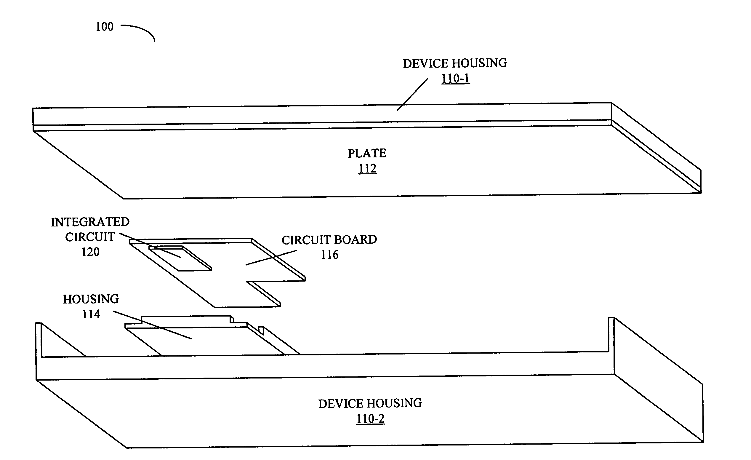
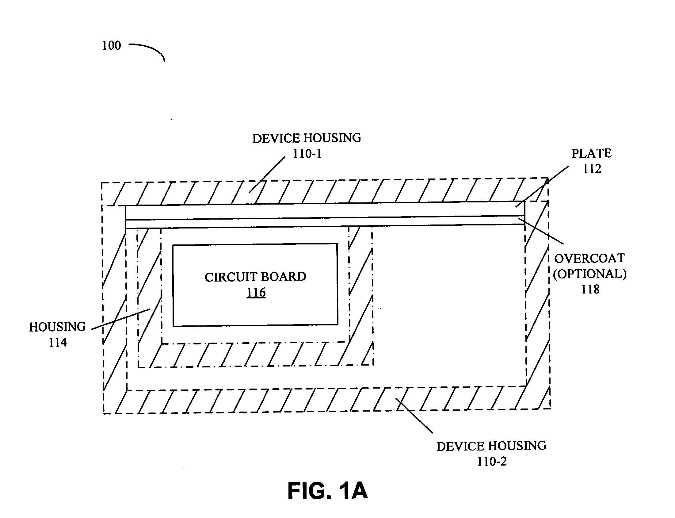
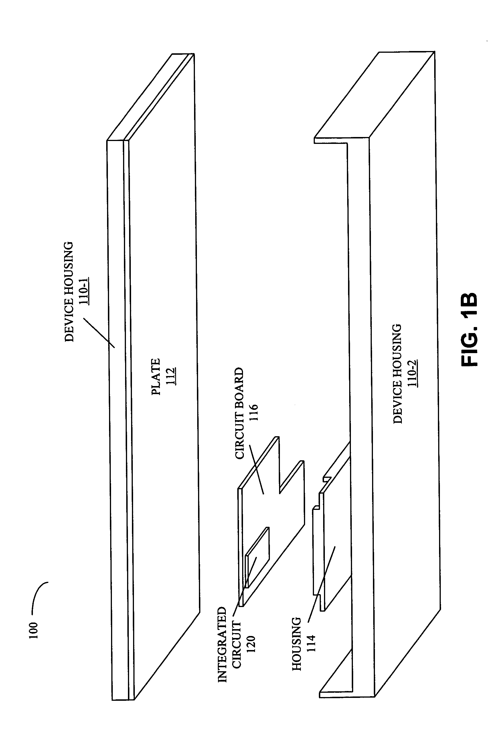
[0023]Embodiments of a system are described that includes a power source and a heat-shield mechanism which encloses the power source. This heat-shield mechanism provides passive cooling of the power source, which may be associated with an integrated circuit. Note that the system may include stationary and / or portable electronic devices (which a...


PUM


Abstract

A system includes a power source and a heat-shield mechanism which encloses the power source. This heat-shield mechanism includes a 3-dimensional housing that defines a cavity in which the power source resides, and a plate that is positioned to cover an opening to the cavity that is defined by an edge of the housing. Note that the housing contains three layers in which a second layer is sandwiched between a first layer and a third layer. This second layer has a first anisotropic thermal conductivity. Furthermore, the plate includes a material having a second anisotropic thermal conductivity.

Description

BACKGROUND[0001]1. Field of the Invention[0002]The present invention relates to heat-transfer techniques. More specifically, the present invention relates to compact, passive cooling components for use in electronic devices.[0003]2. Related Art[0004]The computational performance provided by electronic devices has increased significantly in recent years. This has resulted in increased power consumption and associated heat generation in these products. Consequently, it has become a considerable challenge to manage this thermal load to maintain acceptable internal and external operating temperatures for these devices.[0005]Portable devices, such as laptop computers (notebook PCs), cellular telephones, and personal digital assistants pose additional design constraints. In particular, size and weight limitations in such devices can make it difficult to achieve desired operational temperatures. For example, in many applications the size and weight of metal heat sinks may be prohibitive. I...

Claims


Application Information

Patent Timeline
Patent Type & Authority Applications(United States)
IPC IPC(8): H05K7/20
CPCG06F1/203H05K7/20518H05K7/20481
Inventor ALI, IHAB A.
Owner APPLE INC
Why Eureka
Try Eureka