Handover in a cellular communication system

a cellular communication system and handover technology, applied in the direction of electrical equipment, radio transmission, transmission, etc., can solve the problems of extending the current approach to scenarios where ue, cells are not practical, and the number of small underlay cells within a single macrocell is large, so as to facilitate implementation and improve performance.

Inactive Publication Date: 2008-05-01
MOTOROLA MOBILITY LLC
View PDF20 Cites 97 Cited by
  • Summary
  • Abstract
  • Description
  • Claims
  • Application Information

AI Technical Summary

Benefits of technology

[0015]This may facilitate implementation and / or improve performance. The identifying means may for example be located in the Radio Access Network or Core Network of a 3rd generation cellular communication system such as UMTS. The identifying means may specifically be implemented in a Radio Network Controller (RNC) or a Mobile Switching Center (MSC).

Problems solved by technology

A widespread introduction of such systems would result in a very large number of small underlay cells within a single macrocell.
However, underlaying a macrolayer of a 3G network with a picocell (or microcell) layer creates several issues for the management of handovers of UEs between the different layers.
In particular, 3G communication systems are developed based on each cell having a relatively low number of neighbours and extending the current approach to scenarios wherein the UE may need to consider large numbers of potential neighbour cells is not practical.
One problem of extending current approaches to scenarios where there are many underlaying picocells is how to uniquely and efficiently identify a picocell (or microcell).
Specifically, it is not practically feasible to list every underlay cell as a potential neighbour of the macrocell as this would require very large neighbour lists.
These large neighbour lists would e.g. result in the neighbour list exceeding the maximum allowable number of neighbours in the list, slow UE measurement performance as a large number of measurements would need to be made.

Method used


Image

  • Handover in a cellular communication system
  • Handover in a cellular communication system
  • Handover in a cellular communication system

Examples


Embodiment Construction

[0022]The following description focuses on embodiments of the invention applicable to a CDMA cellular communication system and in particular to a 3rd Generation Cellular communication system such as a UMTS System. However, it will be appreciated that the invention is not limited to this application but may be applied to many other communication systems.

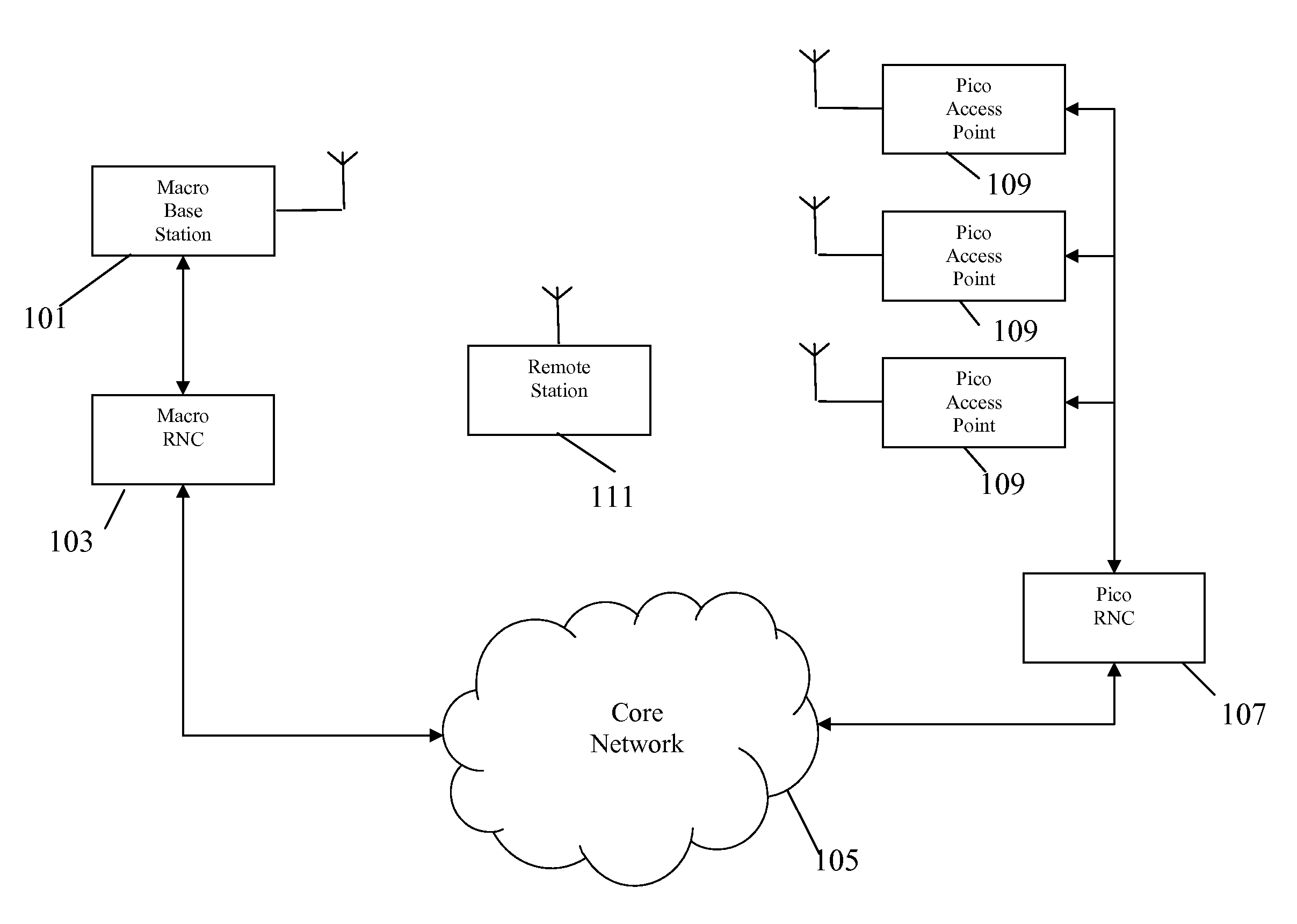
[0023]FIG. 1 illustrates an example of a cellular communication system in accordance with some embodiments of the invention. In the system, a macro-layer is formed by macrocells supported by base stations. Furthermore, an underlay layer of picocells are supported by a large number of access points corresponding to picocell base stations. Specifically, each access point may have an intended coverage of a single house or dwelling, and for a typical macrocell coverage area of 10 to 30 km there may be hundreds or even thousands of picocells each supported by an individual access point.

[0024]In the system, the macro base stations each have...


PUM


Abstract

A cellular communication system includes base stations supporting macro cells and with unique cell scrambling codes within a region. The system further includes access points supporting underlay cells and with shared cell scrambling codes within the region. One or more of the access points or base stations comprise transmit means for transmitting an indication of at least a first shared scrambling code to a remote station. The shared scrambling code is shared by a plurality of access points. The remote station is arranged to receive the first shared scrambling code and to determine if a first signal using the first shared scrambling code is received. If the first signal is detected, a handover controller initiates a handover of the remote station to at least a first access point of the plurality of access points sharing the first shared scrambling code.

Description

FIELD OF THE INVENTION [0001]The invention relates to handover in a cellular communication system and in particular, but not exclusively, to handover to underlay cells in a Code Division Multiple Access (CDMA) cellular communication system.BACKGROUND OF THE INVENTION[0002]A method which has been used to increase the capacity of cellular communication systems is the concept of hierarchical cells wherein a macrocell layer is underlayed by a layer of typically smaller cells having coverage areas within the coverage area of the macrocell. In this way, smaller cells, known as microcells or picocells (or even femtocells), are located within larger macrocells. The microcells and picocells have much smaller coverage thereby allowing a much closer reuse of resources. Frequently, the macrocells are used to provide coverage over a large area, and microcells and picocells are used to provide additional capacity in e.g. densely populated areas and hotspots. Furthermore, picocells can also be use...

Claims


Application Information

Patent Timeline
Patent Type & Authority Applications(United States)
IPC IPC(8): H04B7/216H04W36/04
CPCH04W72/0466H04W36/04
Inventor THOMAS, HOWARD J.FOSTER, GERARD T.HANNA, TREVOR T.IYER, SUBRAMANIAN S.LOPES, LUIS
Owner MOTOROLA MOBILITY LLC
Why Eureka
Try Eureka