Ankle prosthesis with neutral position adjustment

a technology of neutral position and ankle joint, which is applied in the field of ankle prosthesis, can solve the problems of affecting the patient's treatment condition, affecting the patient's balance, and restoring many degrees of freedom that have previously been lost, and achieves good stability of the ankle joint and satisfying joint mobility

Active Publication Date: 2008-05-01
EURO FOOT PLATFORM SC
View PDF4 Cites 89 Cited by
  • Summary
  • Abstract
  • Description
  • Claims
  • Application Information

AI Technical Summary

Benefits of technology

[0013]A feature of the present invention is a novel ankle prosthesis that does not suffer from the above-mentioned drawbacks and that, while offering satisfactory joint mobility, also guarantees good stability to the ankle joint.
[0014]A feature of the present invention is a novel ankle prosthesis that is ergonomic and comfortable during use.
[0015]Another feature of the present invention is a novel ankle prosthesis in which wear is minimized and which offers increased longevity.

Problems solved by technology

Although ankle prostheses offer features that are advantageous in terms of movement, the ankle prostheses can be unsuitable for the condition of the patient being treated.
When the patient has already undergone orthopedic treatment limiting the mobility of the ankle, the joint generally suffers from instability due to being weakened by muscle atrophy and / or to tendon laxity.
Thus, when, for example, consideration is given to performing arthroplasty (joint replacement) serving to restore joint mobility when the joint has been previously immobilized by arthrodesis (joint fusion), or indeed when it is desired to replace a prosthesis that is an old model and whose movement configuration differs from that of the three-implant prosthesis, suddenly restoring many degrees of freedom that have previously been lost tends to disturb the balance of the patient and exposes the patient to risks of falls, of injuries, and of damage to tissue situated at the joint in question.
Therefore, implementing prior art three-implant prostheses requires patients to undergo a very long period of rehabilitation.
In addition, certain national regulatory requirements prohibit the use of prior art three-implant prostheses.

Method used


Image

  • Ankle prosthesis with neutral position adjustment
  • Ankle prosthesis with neutral position adjustment
  • Ankle prosthesis with neutral position adjustment

Examples


Embodiment Construction

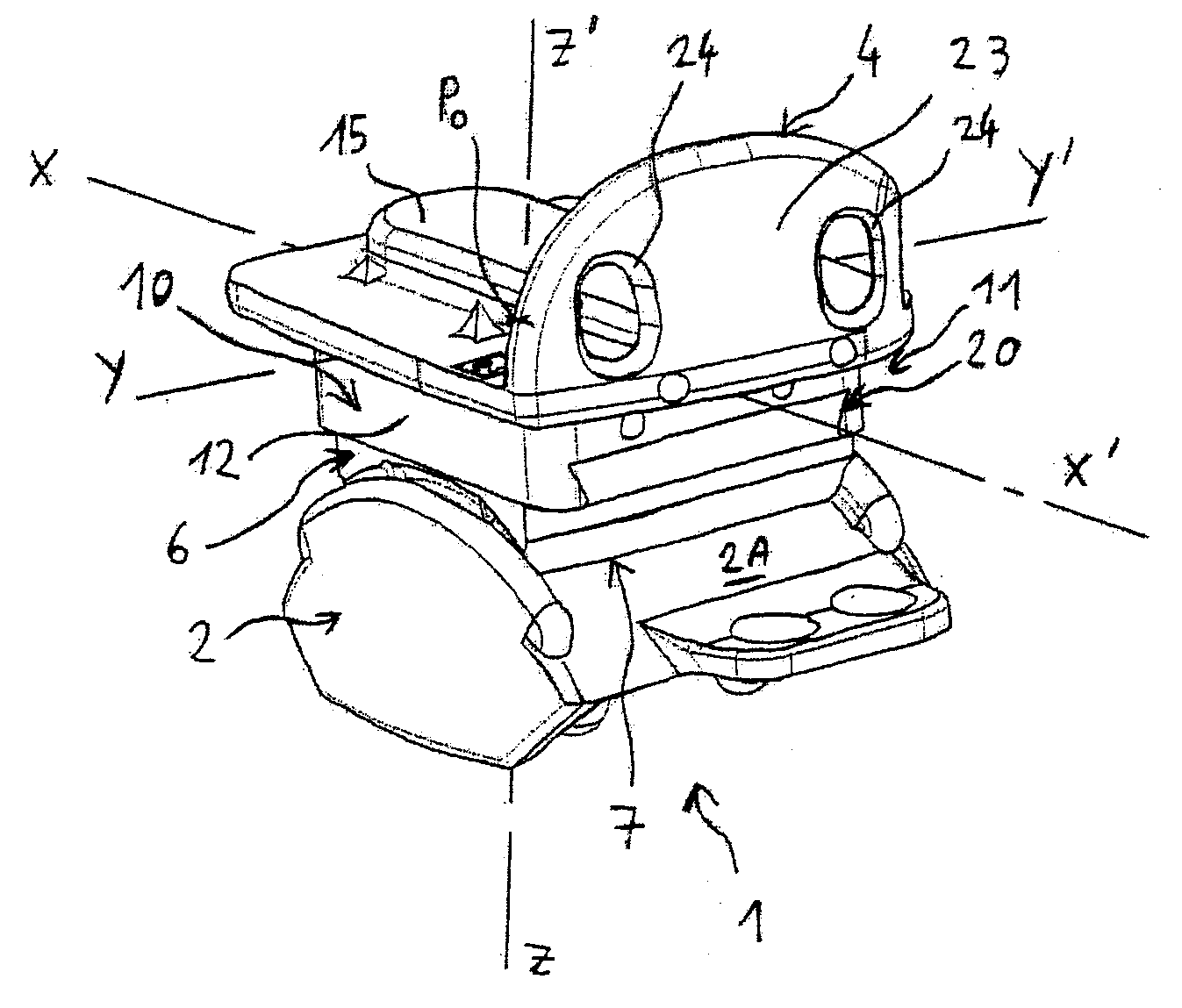
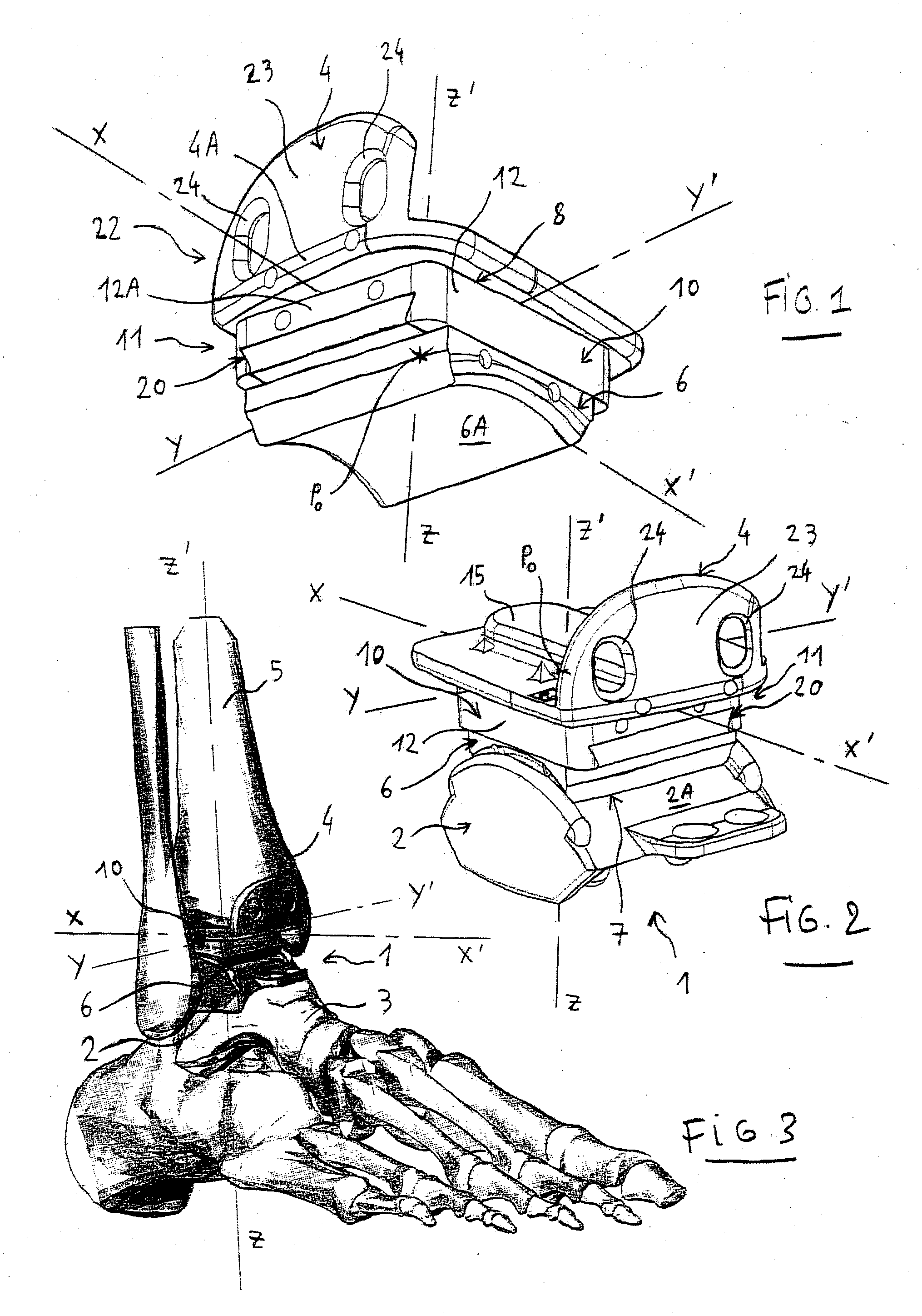
[0041]The ankle prosthesis 1 of the present invention is designed to restore, at least partially, the mobility of an ankle joint in a patient who has, in particular, suffered disease or impact trauma.

[0042]The ankle prosthesis 1 of the present invention can also be used to replace a previously implanted ankle prosthesis.

[0043]The ankle prosthesis 1 of the present invention comprises a talar implant 2 designed to be implanted in or on the talus (anklebone) 3 and a tibial implant 4 designed to be implanted in or on the tibia 5.

[0044]The ankle prosthesis 1 further comprises an intermediate implant 6 which is designed to be interposed between the tibial implant 4 and the talar implant 2.

[0045]The intermediate implant 6 is designed to be mounted to move relative to the talar implant 2 at a contact interface 7, in order to allow the ankle to move. The intermediate implant 6 can, in particular, be made of polyethylene.

[0046]More precisely, the intermediate implant 6 preferably has a contac...


PUM


Abstract

The invention relates to an ankle prosthesis (1) comprising a talar implant (2) designed to be implanted in or on the talus (3), a tibial implant (4) designed to be implanted in or on the tibia (5), and an intermediate implant (6) designed to be interposed between the tibial implant and the talar implant, said intermediate implant (6) being designed to be mounted to move relative to said talar implant (2) at a contact interface (7) in order to allow the ankle to move, said ankle prosthesis (1) being characterized in that it is provided with configurable coupling means (10) designed to enable the intermediate implant (6) to be arranged relative to the tibial implant (4) in a specific configuration chosen from among a plurality of possible configurations.

Description

FIELD OF THE INVENTION[0001]The present invention relates to ankle prostheses designed to orthopedically treat ankle joints; and more particularly, to implants for restoring ankle joint anatomy.[0002]The present invention also relates to a method of preparing an ankle prosthesis as described above.[0003]The present invention also relates to a surgical kit designed for putting an ankle prosthesis into place.[0004]The present invention finally relates to a surgical method of implanting an ankle prosthesis having a talar implant designed to be implanted in or on the talus, a tibial implant designed to be implanted in or on the tibia, and an intermediate implant designed to be interposed between the tibial implant and the talar implant, the intermediate implant being designed to be mounted to move relative to the talar implant at a contact interface in order to allow the ankle to move.BACKGROUND OF THE INVENTION[0005]It is known that ankle prostheses can be used to restore a certain amo...

Claims


Application Information

Patent Timeline
Patent Type & Authority Applications(United States)
IPC IPC(8): A61F2/38
CPCA61F2/4202A61F2002/30398A61F2/4684A61F2002/30387A61F2002/4205A61F2002/4207A61F2002/4658A61F2220/0025A61F2002/30537A61F2002/30393A61F2002/30392A61F2002/30518A61F2002/30542A61F2002/30433A61F2002/30538A61F2002/30329A61F2002/3054A61F2002/30401A61F2/4657A61F2/4606A61F2/468
Inventor HINTERMANN, BEAT
Owner EURO FOOT PLATFORM SC
Why Eureka
Try Eureka