Dispensing Device

a technology of a dispenser and a counter, which is applied in the direction of medical devices, inhalators, other medical devices, etc., can solve the problems of increasing or decreasing the value displayed to the user by the counter, the device is susceptible to unintentional actuation, and the value displayed to the user is often subject to impact and sudden movement, so as to prevent the dispensing of the dose of the medicament formulation

Active Publication Date: 2008-05-08
GLAXO GROUP LTD
View PDF72 Cites 59 Cited by
  • Summary
  • Abstract
  • Description
  • Claims
  • Application Information

AI Technical Summary

Benefits of technology

[0027]This aspect of the invention, and others herein disclosed, is particularly advantageous since a prior art housing may be used. This reverse-compatibility is advantageous for the user, who can fit a closure (e.g. a dust cap) with a restricting member to an existing inhaler that he already owns, to the manufacturer, who is not required to change his manufacturing process for the housing, and also for the marketer, who will not need to seek new regulatory approval for an adapted housing.
[0029]In an embodiment of the invention, such as one hereinafter to be described, the restricting member is configured as a clip that engages a surface of the housing and / or container unit, suitably the stem block and / or a step in the housing. This is advantageous since it secures the closure to the housing whilst the inhaler is not in use. Moreover, it secures the restricting member in its second position. In an embodiment of the invention, such as one hereinafter to be described, the clip configuration of the restricting member is such that, if the container unit is moved in its dispensing direction relative to the housing, it causes the gripping force of the restricting member to increase ensuring that the closure is not ejected and dispensing does not occur.
[0031]Attaching the closure to the housing is a regulatory requirement in the United States and is in any case beneficial since it prevents loss of the closure or swallowing of it by the user. A particular advantage of an extensible connector (e.g. a strap) is that it reduces the force required to engage and disengage the closure. This is particularly important since many users of inhalers are elderly or infirm and may have weak fingers.
[0032]Optionally, the closure may comprise a restricting member. The presence of a restricting member is in itself desirable, as discussed above, and the connector comprised by the present invention is particularly suited to use with closures that comprise a restricting member and that must therefore be spaced sufficiently in front of the housing dispensing outlet that the restricting member can be correctly orientated before the cap is engaged.
[0034]In an embodiment of the invention, such as one hereinafter to be described, the connector is telescopic and may comprise a first component attached to the housing and a second component attached to the closure, wherein the components are slidingly movable relative to each other between a contracted position, wherein the closure closes the dispensing outlet, and an extended position, wherein the closure is spaced from the dispensing outlet. The two components may be connected using a pin on one component that is held captive within a slot in the other component. At least one of the components may comprise hinging means, for example a fold line. Additionally, raised edges may be provided on one of the components, to substantially prevent relative rotational movement of the components.

Problems solved by technology

pMDI devices, however, are susceptible to unintentional actuation, particularly whilst in transit, for example shipment between the manufacturer and distributor.
During such transit, such devices and their packaging are often subjected to impacts and sudden movements.
When the pMDI includes a dose counter, rough handling in transit can cause the value displayed to the user by the counter to increase or decrease so that it is not consistent with the number of doses that have been dispensed by, or remain in, the pMDI.
It is wasteful to dispense unwanted doses of the medicament, and potentially very dangerous for a dose counter to indicate to the user that more doses remain in the canister than are actually present.
There are, however, a number of disadvantages with the Easyhaler® inhaler.
Should moisture enter the inhaler, the powder will agglomerate to form lumps that cannot enter the metering drum, thus affecting the dosage.
Also, the interior surface of the mouthpiece is likely to become moist during use, causing the powdered medicament to stick to its interior surface.
This re-testing delays production and involves additional expense.
Another problem with the prior art Easyhaler® inhaler is that an adapted cap, provided with a prong, can only be used with inhalers that have been specially provided with a hole above the mouthpiece.
The effect of this is that the cap is not reverse-compatible with previously manufactured housings and that the manufacture of the housing needs to be updated.
There are a number of problems with this strap.
Consequently, the dust cap may be difficult for people with weak fingers, for example the arthritic, to apply and remove.
A second problem is that continual folding weakens the fold lines in the strap, which may break after a large number of folding actions.
An additional problem is present in those inhalers that comprise a prong attached to the dust cap.
Accordingly, if the cap is to comprise a prong which must engage, for example, a hole in the housing, the sweeping motion of the prong as the cap rotates would present a problem.

Method used


Image

  • Dispensing Device
  • Dispensing Device
  • Dispensing Device

Examples


first embodiment

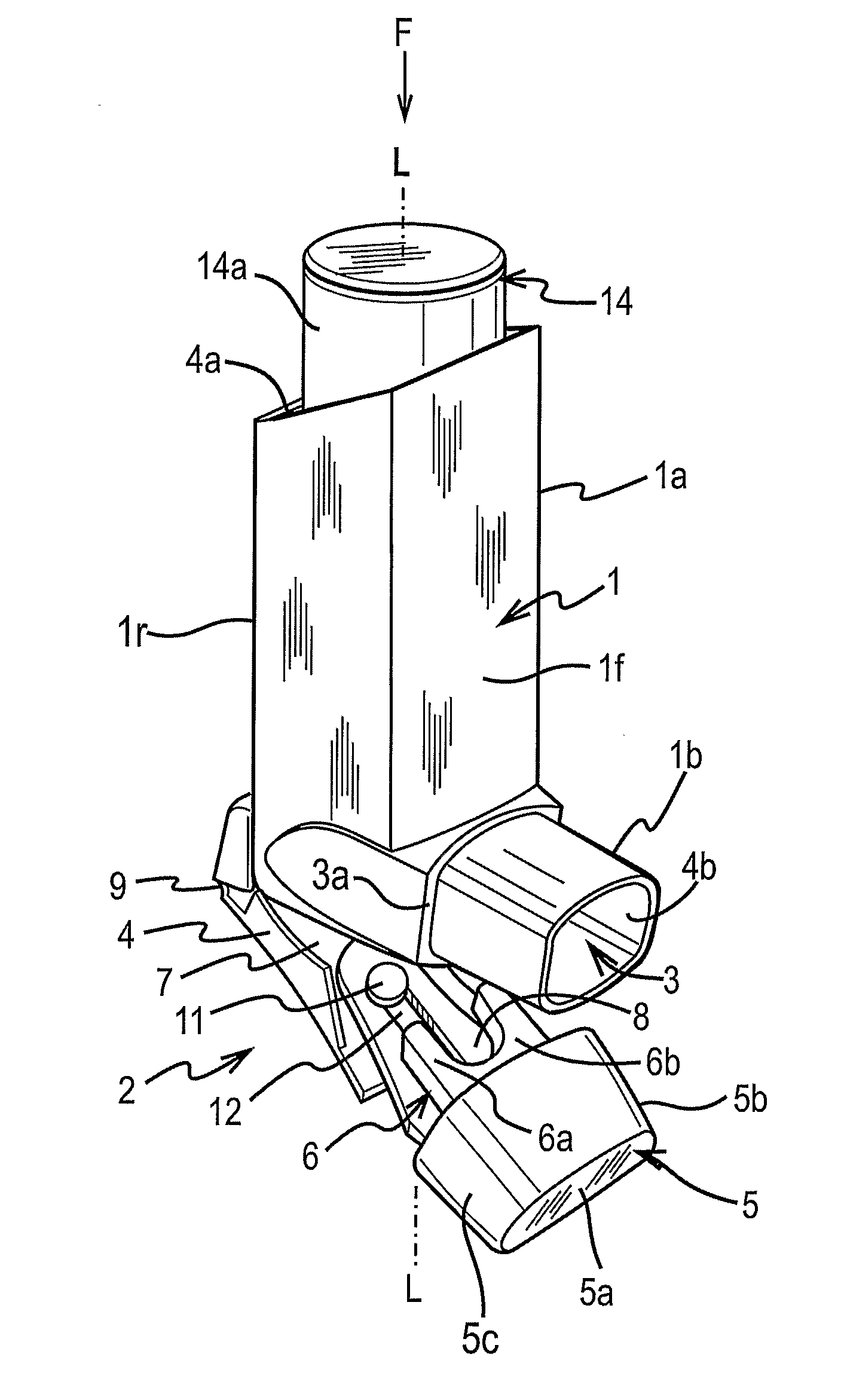
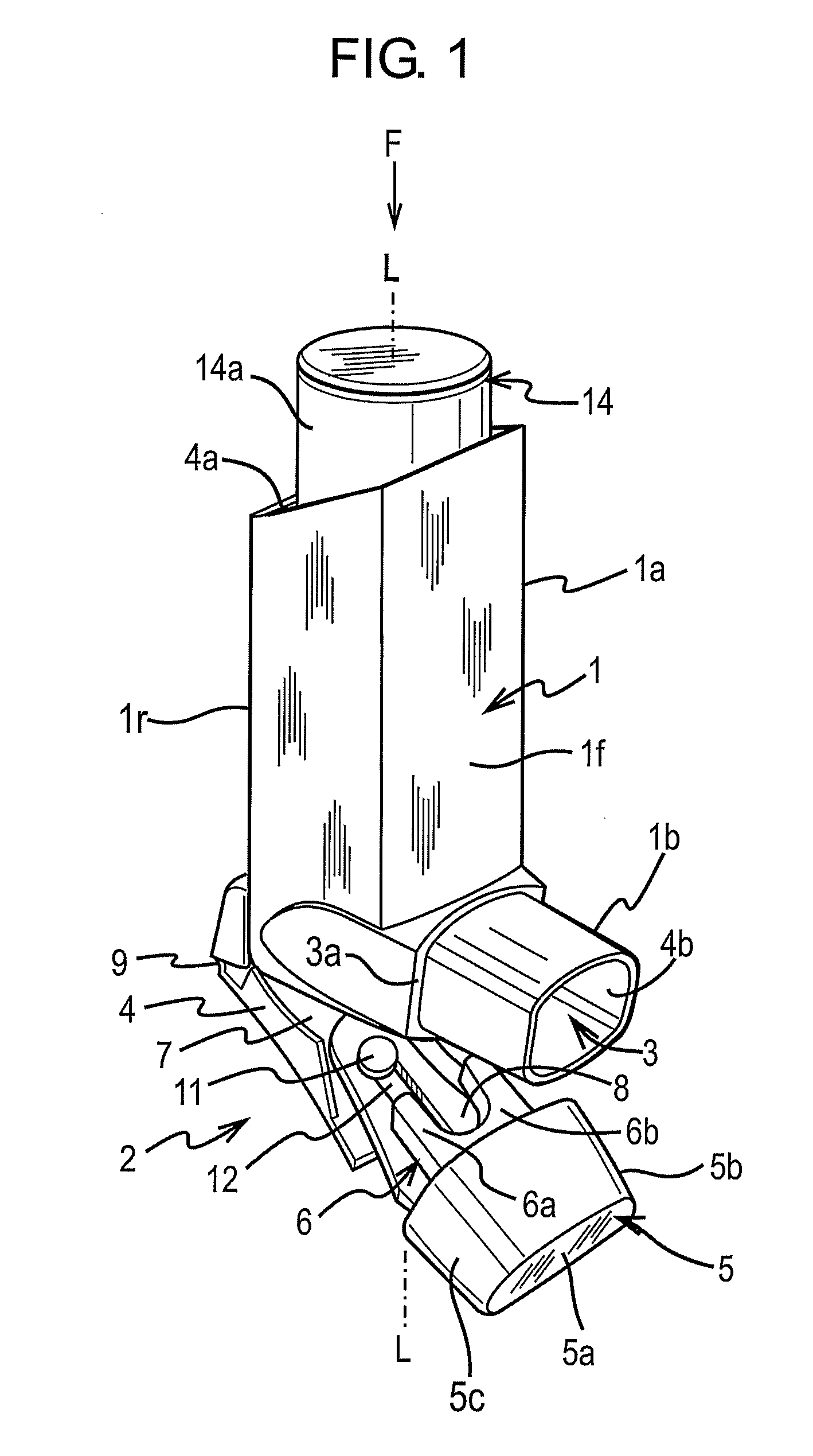
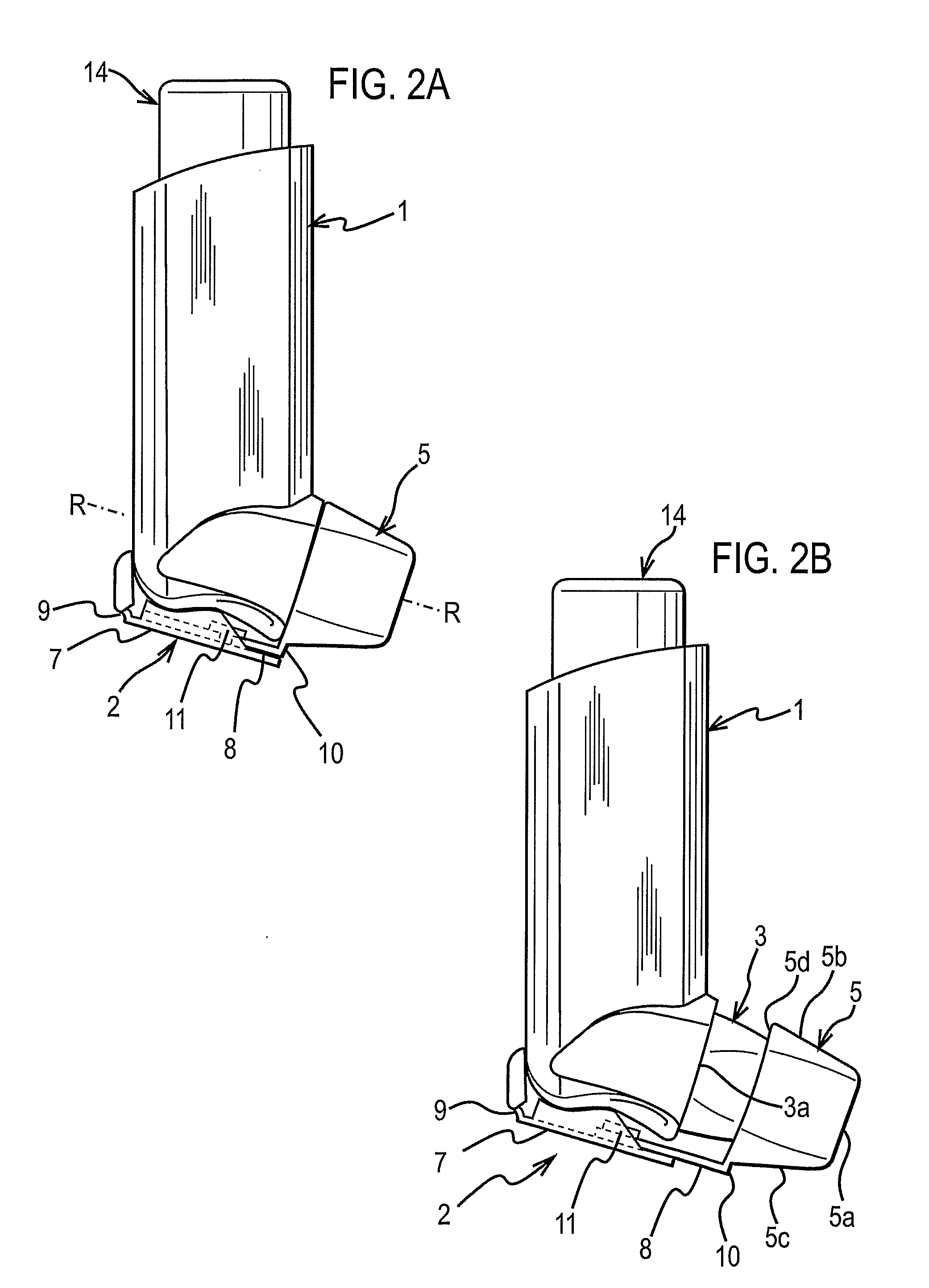
[0068]FIGS. 1 and 2 are respectively front, perspective and side views showing a pMDI according to the present invention. In this embodiment, the pMDI is based on a pMDI known in the prior art, as described in the ‘Background of the Invention’ section supra, although the present invention is not limited to the exact form of such an arrangement.

[0069]The pMDI comprises a canister unit 14 and a housing 1 in which the canister unit 14 is slidable along its longitudinal axis L-L. The housing 1 is generally tubular and of L-shape having an axial section 1a and a transverse section 1b configured as a mouthpiece 3. The housing 1 is preferably moulded from a plastics material, for example by injection moulding. Conveniently, the housing is of polypropylene. In the use orientation of the pMDI shown in FIGS. 1 and 2, the housing 1 has an upper open end 4a in the axial section 1a, through which the canister unit 14 is reversibly slidable into the housing 1, and a lower open end 4b in the mouth...

second embodiment

[0087]In the second embodiment the first component 7 of the telescopic strap 2 has a distal track member 7a with opposed side walls 4. At the distal end of the track member 7a the side walls 4 are bridged by a bridging element 4c. At the proximal end of the first component 7 there is a hinge member 7b which is secured to the housing 1. The track and hinge members 7a, 7b are hinged together by the hinge 9 whereby the track member 7a is hingable about the hinge member 7b.

[0088]As regards the second component 8 of the telescopic strap 2, this has a proximal slide member 8a which is linearly slidable in the track member 7a and guided in its linear stroke by the side walls 4. The slide member 8a has a resilient finger 8m at its proximal end which presents a stop element 8b which engages with the bridging element 4c to demark the extended position of the strap 2 and to keep the slide member 8a captive in the track member 7a. At the distal end of the second component 8 there is provided a...

third embodiment

[0099]In the invention, shown in FIGS. 4A and 4B, the dust cap 5 has elongated sides 13 which are disposable on opposed sides of the lateral section 1b of the housing 1. A pin 16 is provided on each side of the housing lateral section 1b. Each elongated side 13 of the dust cap 5 has a slot 15 along its length, which has closed ends. The slots 15 hold the pins 16 captive. The arrangement of the slots 15 and pins 16 secures the dust cap 5 to the housing 1, whilst permitting the dust cap 5 to be rotated about the common axis A-A of the pins 16 and moved towards and away from the mouthpiece 3 along the length of the slots 15.

[0100]To remove the dust cap 5, the user pulls it away from the mouthpiece 3, sliding the pins 16 within the slots 15. The user then rotates the dust cap 5 about the pins 16, swinging it below the housing 1 to prevent it obstructing the mouthpiece 3. The dust cap 5 is then reapplied by swinging it back into a position in front of the mouthpiece 3 and then sliding it...


PUM


Abstract

An inhaler is provided with a restricting member to prevent unintentional actuation of the inhaler. Also provided is an inhaler with an extensible strap joining a dust cap to the housing of an inhaler, the strap being particularly suited for use with inhalers that comprise a restricting member. The inhaler is useful, for example, in the treatment of asthma.

Description

RELATED APPLICATIONS[0001]This patent application claims priority from UK patent application Nos. 0 405 397.1 and 0 420 538.1 respectively filed on 10 Mar. 2004 and 15 Sep. 2004, the entire contents of each of which are incorporated herein by reference.FIELD OF THE INVENTION[0002]The present invention relates to a dispensing device for dispensing a substance, and is particularly, but not exclusively, concerned with a medicament dispenser from which a medicament formulation is dispensable. The invention also relates to a closure and to an accessory for a dispensing device, for instance a medicament dispenser.[0003]An example of a medicament dispenser to which the invention is particularly, but not exclusively, concerned is an inhaler, for instance a pressurised metered dose inhaler (hereinafter referred to as a “pMDI”). The invention does, however, embrace other inhaler types, for example a dry powder inhaler (DPI), as will be appreciated by the reader skilled in the inhaler art.BACK...

Claims


Application Information

Patent Timeline
Patent Type & Authority Applications(United States)
IPC IPC(8): A61M11/00A61M11/02A61M15/00B65D83/14
CPCA61M15/009A61M2205/276A61M2205/6045A61M15/0096A61M15/00A61M15/0023A61M15/0025A61M11/04A61M15/0076A61M15/0081A61M15/0095A61M15/0026
Inventor PEARSON, ALLEN JOHNANDERSON, GREGOR JOHN MCLENNANBRAND, PETER JOHNCOX, MARK ANTHONYCUDE, IANFARR, PHILLIP WILLIAMKELLY, ANDREW MICHAELLINTELL, DANIEL THOMAS DE SAUSMAREZRAND, PAUL KENNETH
Owner GLAXO GROUP LTD
Why Eureka
Try Eureka