Clutch Mechanism

a technology of clumping mechanism and agitator, which is applied in the direction of toothed gearings, couplings, applications, etc., can solve the problems of belt deterioration, belt deterioration, and difficulty in sensing overload conditions, so as to reduce the likelihood of nuisance tripping and prevent unwanted activation of overload means

Inactive Publication Date: 2008-05-08
DYSON TECH LTD
View PDF33 Cites 32 Cited by
  • Summary
  • Abstract
  • Description
  • Claims
  • Application Information

AI Technical Summary

Benefits of technology

[0011]The provision of an actuator that is activated by the temperature rise caused by slippage of the friction surfaces, or the speed of rotation of the slipping surfaces, ensures that transmission of torque is interrupted when the load on the agitator exceeds a predetermined value. Furthermore, the invention reduce...

Problems solved by technology

A problem which may be encountered with vacuum cleaners having an agitator is that, on occasion, the agitator may become jammed by becoming entangled with objects on the floor surface, for example, or by being pressed hard into the floor.
However, where the agitator is driven by the vacuum motor, sensing of such overload conditions is more difficult.
However,...

Method used


Image

  • Clutch Mechanism
  • Clutch Mechanism
  • Clutch Mechanism

Examples


Embodiment Construction

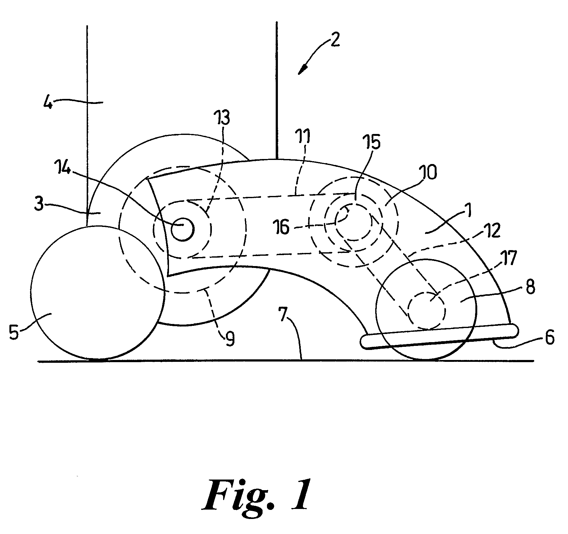
[0018]FIG. 1 illustrates schematically the cleaner head 1 of a vacuum cleaner, indicated generally by the reference numeral 2. The cleaner head 1 is pivotably mounted on a motor housing 3 located at the lower end of a main body 4 in which dust-separating apparatus (not shown) is housed. The dust separating apparatus may take the form of a dust bag, cyclonic separator or other filter. A pair of wheels 5 is also mounted on the motor housing 3, from which the cleaner head 1 extends in a forward direction.

[0019]The cleaner head 1 has a dirty air inlet 6 located at its forward end and facing downwardly so that, in use, the dirty air inlet 6 rests on the surface 7 to be cleaned, which usually a floor or carpet. An agitator in the form of a brush bar 8 is rotatably mounted in a known manner by means of bearings (not shown) so that the brush bar 8 extends across substantially the entire width of the dirty air inlet 6. The brush bar 8 protrudes slightly out of the dirty air inlet 6 so as to ...


PUM


Abstract

A clutch mechanism includes clutch members having an engaged position, in which torque generated by a drive is transmitted to an output, and a disengaged position, in which torque is not transmitted to the output. The clutch members are capable of slipping with respect to each other in order to prevent damage caused by overload conditions. The clutch mechanism further comprises an actuator associated with a clutch member. If the clutch members slip and a characteristic associated with slipping of the clutch members, such as the temperature rise of the slipping surfaces or the relative rotational speed of the clutch members is above a predetermined value, transmission of torque to the output is interrupted. The clutch mechanism is particularly suited for inclusion in a drive mechanism for the agitator of a surface treating appliance, such as a vacuum cleaner.

Description

REFERENCE TO RELATED APPLICATIONS[0001]This application is a national stage application under 35 USC 371 of International Application No. PCT / GB2005 / 003251, filed May 5, 2005, which claims the priority of United Kingdom Application No. 0410081.4, filed May 6, 2004, the contents of both of which prior applications are incorporated herein by reference.FIELD OF THE INVENTION[0002]This invention relates to a clutch mechanism, such as that employed in conjunction with the drive of the agitator of a vacuum cleaner.BACKGROUND OF THE INVENTION[0003]Vacuum cleaners typically comprise a downwardly directed dirty-air inlet arranged in the cleaner head or a floor tool, through which dirty air is sucked, by means of a motor-driven fan, into dirt and dust separation apparatus. An agitator, such as a brush bar, may be arranged in the mouth of the dirty air inlet so as to agitate the fibres of a carpet over which the vacuum cleaner is passed. The agitator helps to release dirt and dust trapped in t...

Claims


Application Information

Patent Timeline
IPC IPC(8): A47L5/30F16H25/08G05B15/00A47L5/22A47L9/04A47L9/22F16D7/02F16D9/02F16D43/25F16H1/28
CPCA47L5/22A47L5/30A47L9/0411A47L9/0438Y10T74/18024F16D7/025F16D9/02F16D43/25F16H1/28A47L9/22
Inventor BURLINGTON, GUY JAMESTOWNSEND, MARTIN DAVID
Owner DYSON TECH LTD
Why Eureka
Try Eureka