
Portal Device

a technology of portal device and port, which is applied in the field of portal device, can solve problems such as surgical compromise, and achieve the effect of preventing accidental removal or intra-operative movement of the portal devi

Active Publication Date: 2008-05-08
CANNUFLOW INC
View PDF3 Cites 27 Cited by
  • Summary
  • Abstract
  • Description
  • Claims
  • Application Information

AI Technical Summary

Benefits of technology

[0005] Embodiments of the present invention provide a system and method for preventing the accidental removal or intra-operative movement of a portal device from an opening in a patient.
[0007] The present invention can also be viewed as providing methods for maintaining an opening formed in a patient. In this regard, one embodiment of such a method, among others, can be broadly summarized by the following steps: inserting a first elongated structure and a second elongated structure through an opening and then moving the first elongated structure relative to the second elongated structure, thereby causing an outside dimension of the second structure to increase in size.

Problems solved by technology

A potential problem with the use of these existing portal devices is they typically have smooth outside surfaces that provide little or no resistance to undesirable or untimely removal of the device.
If a portal device is inadvertently extracted from an opening in a patient during surgery, this could create clinical or time related problems associated with, for example, replacing, resituating the portal device, or re-sterilizing the portal device.
Another problem seen with the existing devices is the unwanted movement into and out of the accessed space, which is a cause for delays or may compromise surgical results.

Method used


Image

  • Portal Device
  • Portal Device
  • Portal Device

Examples


first embodiment

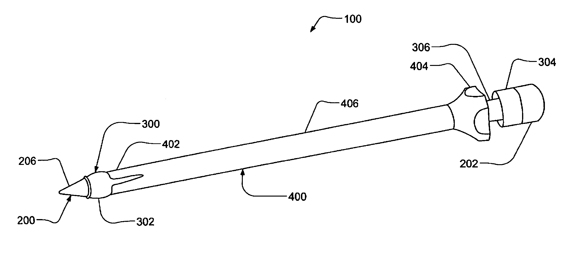
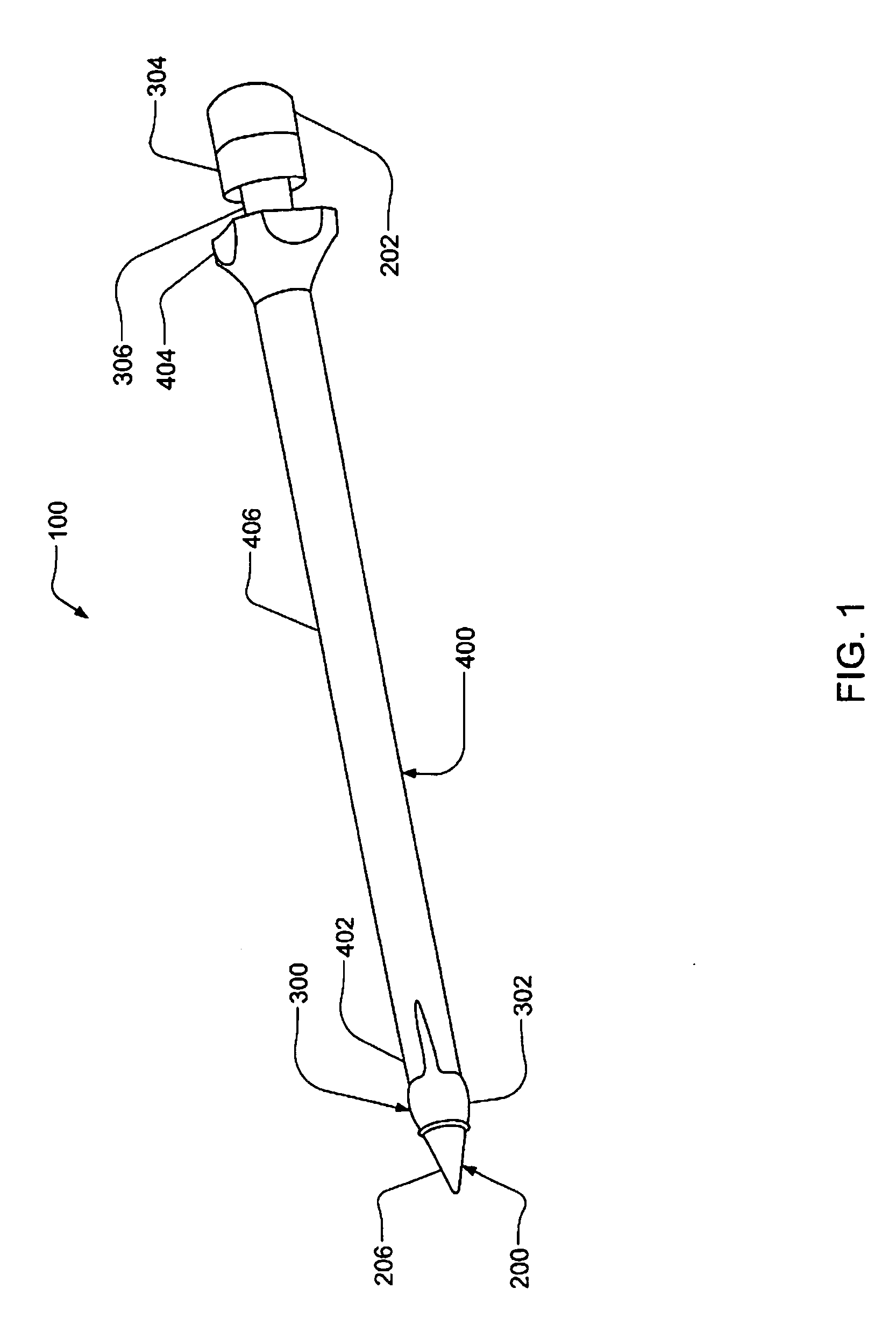
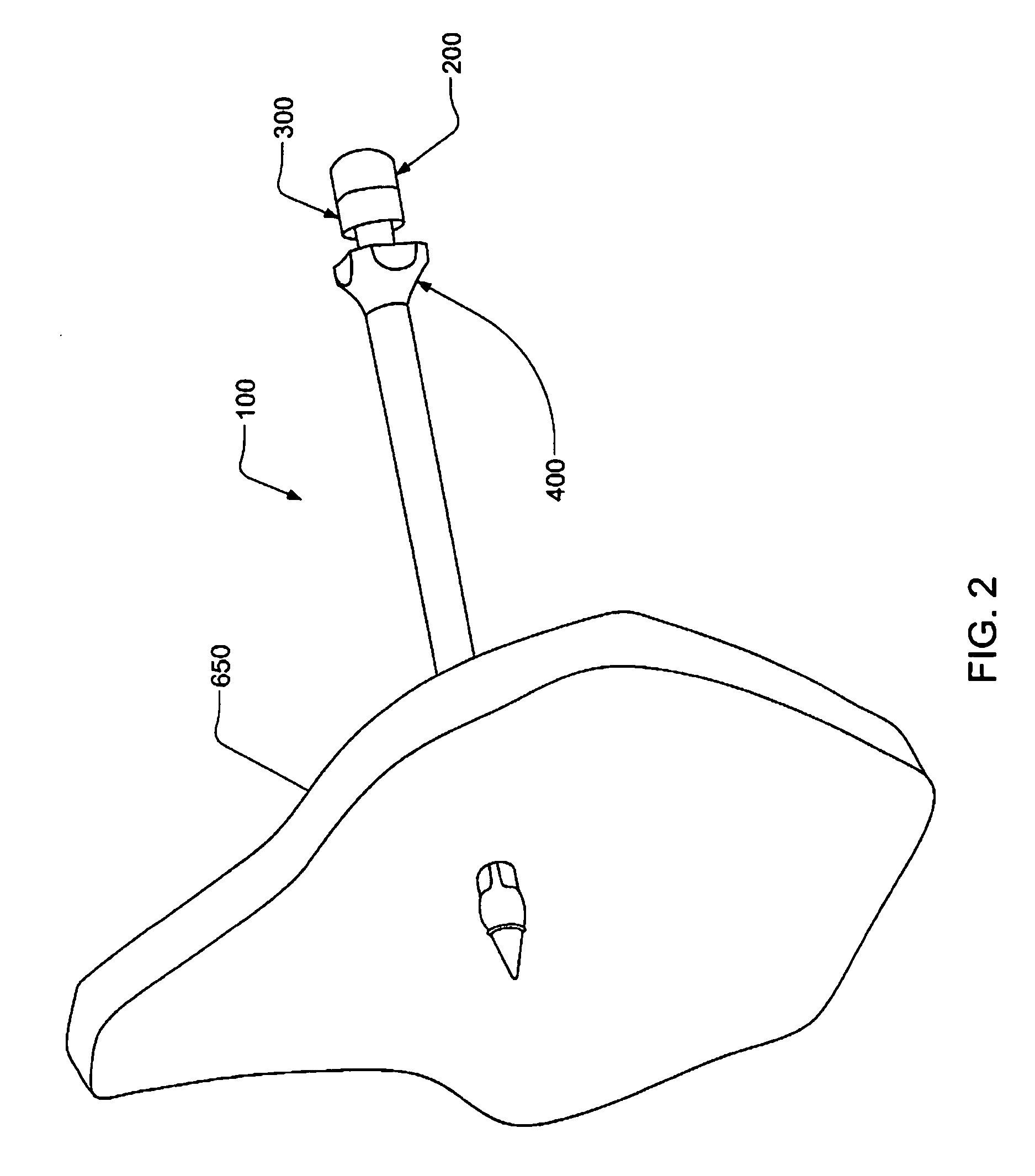
[0034]FIG. 1 shows a portal device 100 in a first position. The device 100 comprises an obturator 200, an inner sheath 300, and an outer sheath 400. The obturator 200 is preferably made of 17-4 PH SS, while the inner sheath 300 and outer sheath 400 are preferably made of a biocompatible plastic. Other materials that are compatible with living tissue by not being toxic, injurious, or causing immunological reaction may be used without departing from the present invention. FIG. 2 shows the portal device 100 after insertion through the skin 650 of a patient.

[0035]FIG. 3 shows the portal device 100 in a second position after the obturator 200 has been withdrawn and flexible tabs 402, to be described in detail in FIGS. 6A-6C, on the outer sheath 400 have been repositioned by a protrusion 302, to be described in detail in FIGS. 7A & 7B, on the inner sheath 300.

[0036]FIG. 4 shows the portal device 100 in the second position after being inserted a sufficient distance through skin 650 of a p...

fourth embodiment

[0051]FIG. 12A shows a fourth embodiment portal device. As shown in FIG. 12A, the inner sheath has a lip 654 adjacent the first end 602 that engages with a first end 652 of the outer sheath 604 to couple the inner sheath to the outer sheath.

[0052] In an alternative embodiment, the inside surface of the outer sheath 604 and the outside surface of the inner sheath 602 may comprise cooperating threads. To move the inner sheath 602 relative to the outer sheath, the surgeon may rotate the inner sheath 602 relative to the outer sheath 604.

[0053]FIG. 13A shows a portal device 500 including a sheath 510, a probe 502, and a is plate 520. The device 500 may be made from a biocompatible material. The sheath 510 may have a first end 512, a middle portion 516, and a second end 514. The middle portion 516 may have an externally formed thread 524. An opening 532 may extend from the first end 512 to the second end 514 and may be sized to allow the probe 502 to extend therethrough. A plurality of t...


PUM


Abstract

A portal device maintains an opening in the skin of a patient to allow for the passage of surgical device therethrough. Tabs disposed at one end of the portal device may be used to resist removal of the device, retract soft tissue from the operative site, and seal the opening to prevent the escape of gases or liquids.

Description

CROSS-REFERENCE TO RELATED APPLICATION [0001] This application claims the benefit of copending U.S. provisional patent application Ser. No. 60 / 377,097 filed on May 2, 2002 and entitled “Portal Device,” the teachings of which are incorporated herein by reference in their entirety.FIELD OF THE INVENTION [0002] The present invention relates generally to a portal device and more particularly to an access port or sleeve for passing surgical instruments into a body. BACKGROUND OF THE INVENTION [0003] Surgeons routinely perform laproscopic and arthoscopic surgery on different body parts of patients. These types of endoscopic surgeries, or other surgeries where an endoscopic-type opening are maintained, are preferred over conventional surgery due to the lower risk of infection to the patient and quicker recovery times. Creating an opening in the skin of the patient commences the surgery. The opening is maintained by the insertion of a portal device. During the course of the surgery, surgica...

Claims


Application Information

Patent Timeline
IPC IPC(8): A61B17/02A61B1/32
CPCA61B1/32A61B17/34A61B2017/3492A61B2017/3484A61B17/3421
Inventor KUNKEL, SANFORD S.DAHLINGER, ERIC F.
Owner CANNUFLOW INC
Learn More