
Heated epoxy cartridges

a technology of epoxy and cartridges, applied in the direction of heating element shapes, coatings, liquid spraying apparatuses, etc., can solve the problems of difficult use of products, slow and expensive, tedious use and application of epoxy compounds, etc., and achieve the effect of promoting their spray application

Active Publication Date: 2017-05-04
WARREN ENVIRONMENTAL & COATING LLC
View PDF9 Cites 6 Cited by
  • Summary
  • Abstract
  • Description
  • Claims
  • Application Information

AI Technical Summary

Benefits of technology

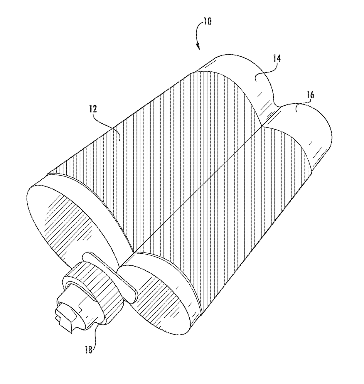
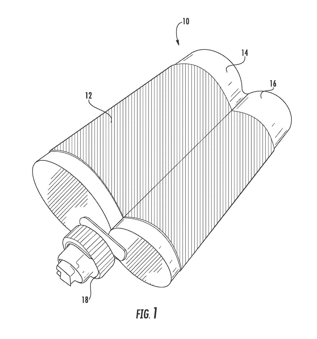
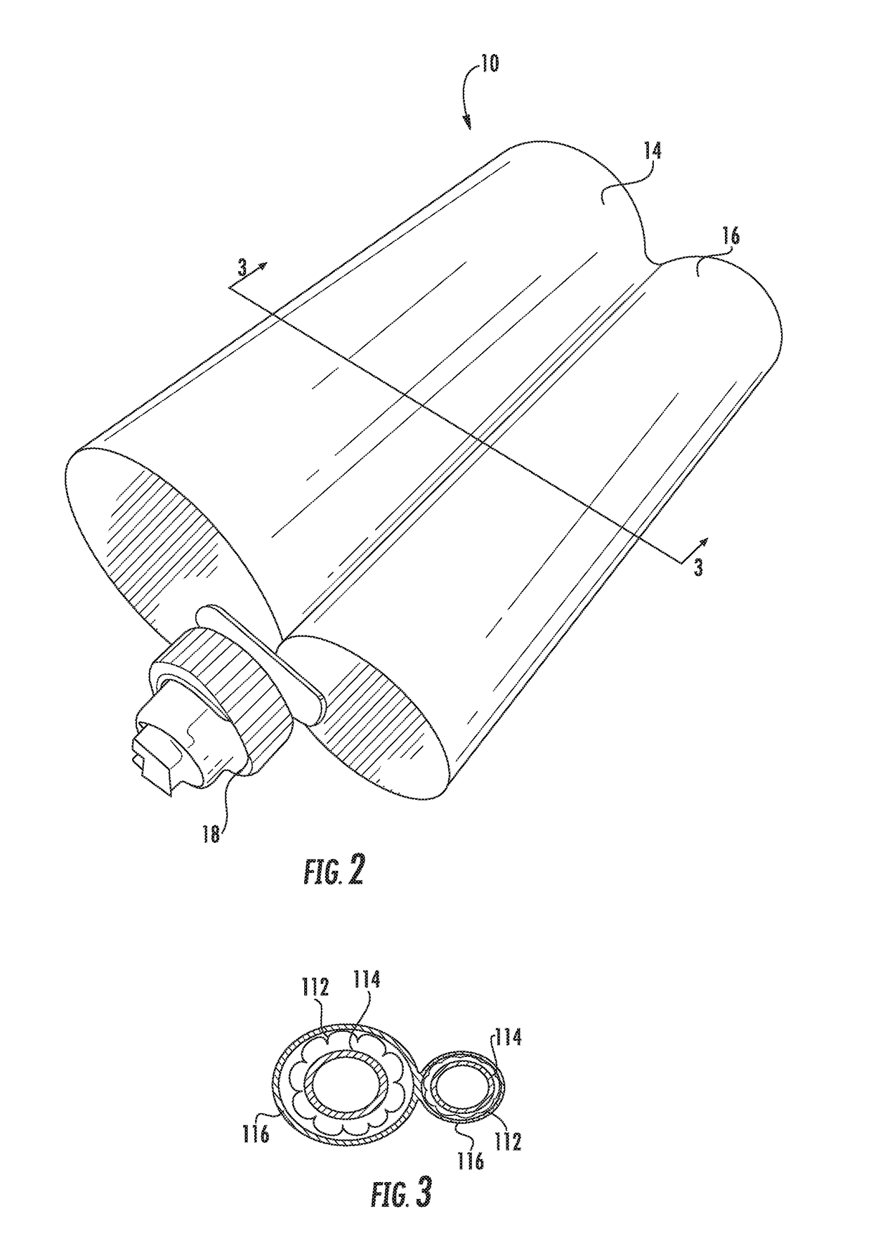
The present invention is a new and improved device for heating high-viscosity materials, such as epoxy, that are used in construction. The device uses a rigid cartridge made of reinforced fiberglass tubing, which is heated by a flexible heating element or embedded cast within the cartridge wall. This new heating method avoids burning the material and ensures consistent and uniform spray application. The device is economically desirable due to the fact that none of the material is burned.

Problems solved by technology

Accordingly, the use and application of these compounds is a tedious, slow and expensive proposition.
This product, like most prior art coatings, has been difficult to use due to the preferred method of spray application.
When attempting to spray apply an epoxy, two drawbacks are encountered.
First, the material cannot be mixed in large batches prior to application because of the short pot life of the material.
Second, the naturally viscous consistency of the mixed epoxy material is not well suited for spray application.
The addition of the solvent to the epoxy coating material in turn greatly increases the VOC content of the epoxy coating material and reduces the build thickness of the finished and cured coating.
More specifically, due to the nature of a mixture of compounds that may be in use, a desired finish may not be attainable if the compounds are applied too thickly.
Applying multiple coats necessarily requires additional time and energy, and therefore can be costly.
In contrast, attempts to apply a thick coating typically result in slumping of compound and may require considerable rework.
In some environments, such as with underground piping, misapplication can be virtually disastrous.

Method used


Image

  • Heated epoxy cartridges
  • Heated epoxy cartridges
  • Heated epoxy cartridges

Examples


Embodiment Construction

[0026]Disclosed herein is a heating assembly that is formed as an integrated part of pre-loaded, two part epoxy cartridges, which heats them in a controlled manner for spray application. Further, the heating assembly is configured and arranged to be reinforced to resist pressure deformation and to facilitate easy spray application of material having a much higher viscosity than was possible in the prior art.

[0027]In the prior art epoxy is loaded into cartridges having two dispensing tubes arranged side by side wherein the size of the two tubes is proportional to the mixing formula of the epoxy wherein one tube is usually smaller and one is larger. This allows two cartridges to neatly nest with one another within a rectangular space wherein the cartridges are flipped relative to one another such that the larger diameter tubes are positioned adjacent the smaller diameter tubes. The cartridges are placed into a piston system that applies pressure to the plungers in the cartridges to fo...


PUM


Abstract

An improved cartridge structure that both heats the materials contained therein and provides for enhanced structure such that the bypass leaking of the low viscosity heated components is avoided. The cartridge is preferably formed from a rigid material such as reinforced fiberglass tubing. The wall of the cartridge is then wrapped in a flexible heating element or has a heating element cast directly in the wall thereof. The heating elements preferably heat the interior contents and epoxy cartridges to between 150 degrees and 180 degrees Fahrenheit. The wall structure may be of single wall construction with the heaters embedded therein or of a double wall construction such that the heaters are contained between an inner and outer wall. Further the wall construction is preferably formed to withstand the pressures applied when spray applying the epoxy contained therein to prevent the tube wall deformation and resulting blow by leakage.

Description

CROSS-REFERENCE TO RELATED APPLICATIONS[0001]This application is related to and claims priority from earlier filed US Provisional Patent Application No. 62 / 248,089, filed Oct. 29, 2015.BACKGROUND OF THE INVENTION[0002]The present invention generally relates to self-heating cartridges containing two-part and / or self-setting compositions prior to their application. More specifically, the present invention relates to a system for efficiently and conveniently preheating prefilled cartridges containing viscous materials such as epoxies, caulking and the like to a temperature that promotes their smooth mixing and application as well as promoting a self-setting reaction.[0003]Cartridges containing viscous materials such as caulking and a variety of two part materials in which mutually reactive liquids need to be mixed prior to their application. A preheating system is needed for maintaining the resin component or any of the components that must be in a preheated ready to use state so that ...

Claims


Application Information

Patent Timeline
Patent Type & Authority Applications(United States)
IPC IPC(8): B05B7/16B05B7/22
CPCB05B7/166B05B7/26B05B7/22B05C17/00523B05C17/00553H05B3/40
Inventor WARREN, PHILIP
Owner WARREN ENVIRONMENTAL & COATING LLC
Learn More