Control system and method for internal combustion engine
- Summary
- Abstract
- Description
- Claims
- Application Information
AI Technical Summary
Benefits of technology
Problems solved by technology
Method used
Image

Examples
Embodiment Construction
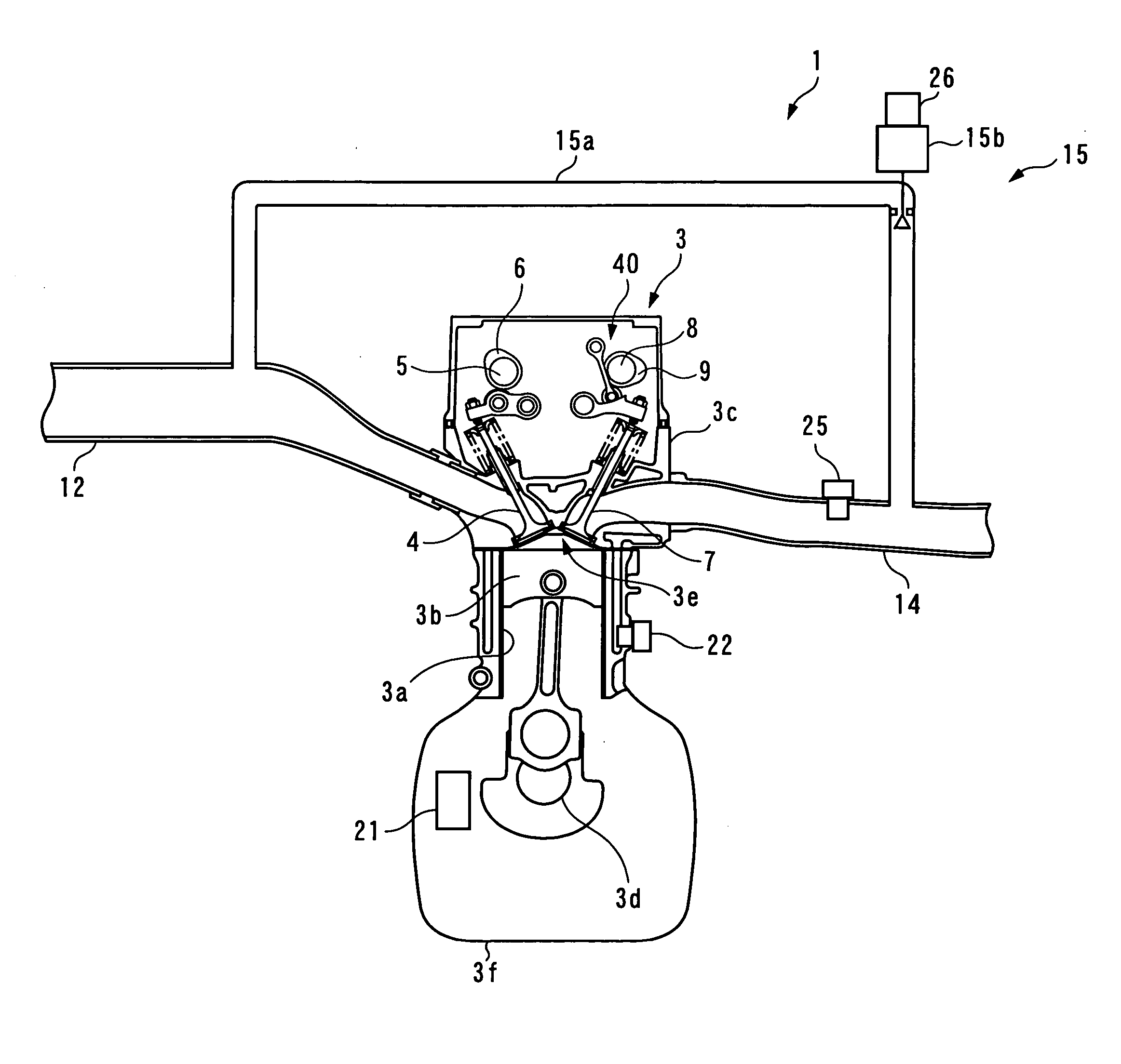
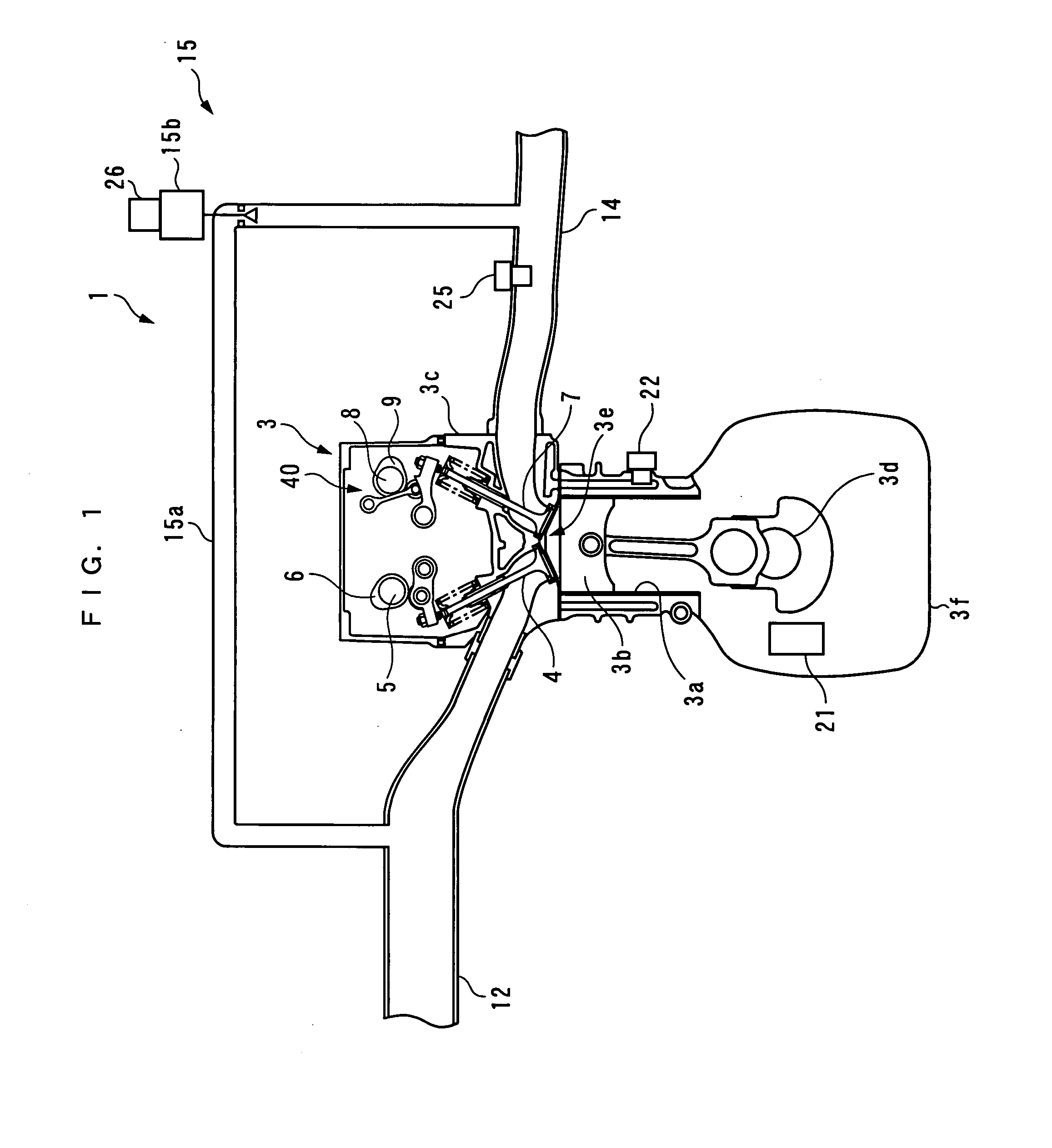
[0031] Hereafter, the invention will now be described in detail with reference to drawings showing preferred embodiments thereof. FIG. 1 schematically shows the arrangement of a control system 1, and an internal engine (hereinafter referred to as “the engine”) 3 to which the internal EGR control system 1 is applied. The engine 3 is an inline four-cylinder gasoline engine installed on an automotive vehicle, not shown, and has four cylinders 3a (only one of which is shown). The engine 3 has a combustion chamber 3e defined between the piston 3b in each cylinder 3a and a cylinder head 3c.
[0032] The engine 3 includes a pair of intake valves 4 and 4 (only one of which is shown) and a pair of exhaust valves 7 and 7 (only one of which is shown), provided on a cylinder-by-cylinder basis. Further, the engine 3 includes an intake camshaft 5 on the intake side and intake cams 6 integrally formed with the intake camshaft 5, an exhaust camshaft 8 on the exhaust side and exhaust cams 9 integrally...
PUM
 Abstract
Description
Claims
Application Information
PatSnap Eureka turns technology decisions into work you can execute. Powered by our Innovation Knowledge Graph, it runs expert workflows across engineering, life sciences, materials and intellectual property. Get your review-ready output in minutes.


