Explosion Pressure Relief Device

a pressure relief device and pressure relief technology, applied in the direction of functional valve types, containers, large containers, etc., can solve the problems of considerable cost for users, the pressure relief device cannot be used again to prevent the exit of an explosion, etc., and achieve the effect of increasing stability

Active Publication Date: 2008-05-15
REMBE
View PDF5 Cites 7 Cited by
  • Summary
  • Abstract
  • Description
  • Claims
  • Application Information

AI Technical Summary

Benefits of technology

[0014]Between the openings for the fastening element, each strut has at least one further through opening (e.g. in the form of a bore) which extends substantially transverse to the longitudinal direction of the strut and in which a holding element is disposed, in accordance with another preferred embodiment. For a cylindrical explosion pressure relief device, this holding element preferably is ring-shaped. The ring-shaped holding element preferably is formed by a flat section, which extends substantially vertical to the longitudinal direction of the struts and provides additional stability to the framework in the case of a pressure relief event and prevents the outward bulging of the wall disposed inside the holding element.

Problems solved by technology

In the case of a pressure relief event performed by the explosion pressure relief device, the wall frequently is clogged by the escaping combustion and expansion gases as well as dusts, so that the pressure relief device cannot be used once again for preventing the exit of an explosion.
This involves considerable costs for the user.

Method used


Image

  • Explosion Pressure Relief Device
  • Explosion Pressure Relief Device
  • Explosion Pressure Relief Device

Examples


Embodiment Construction

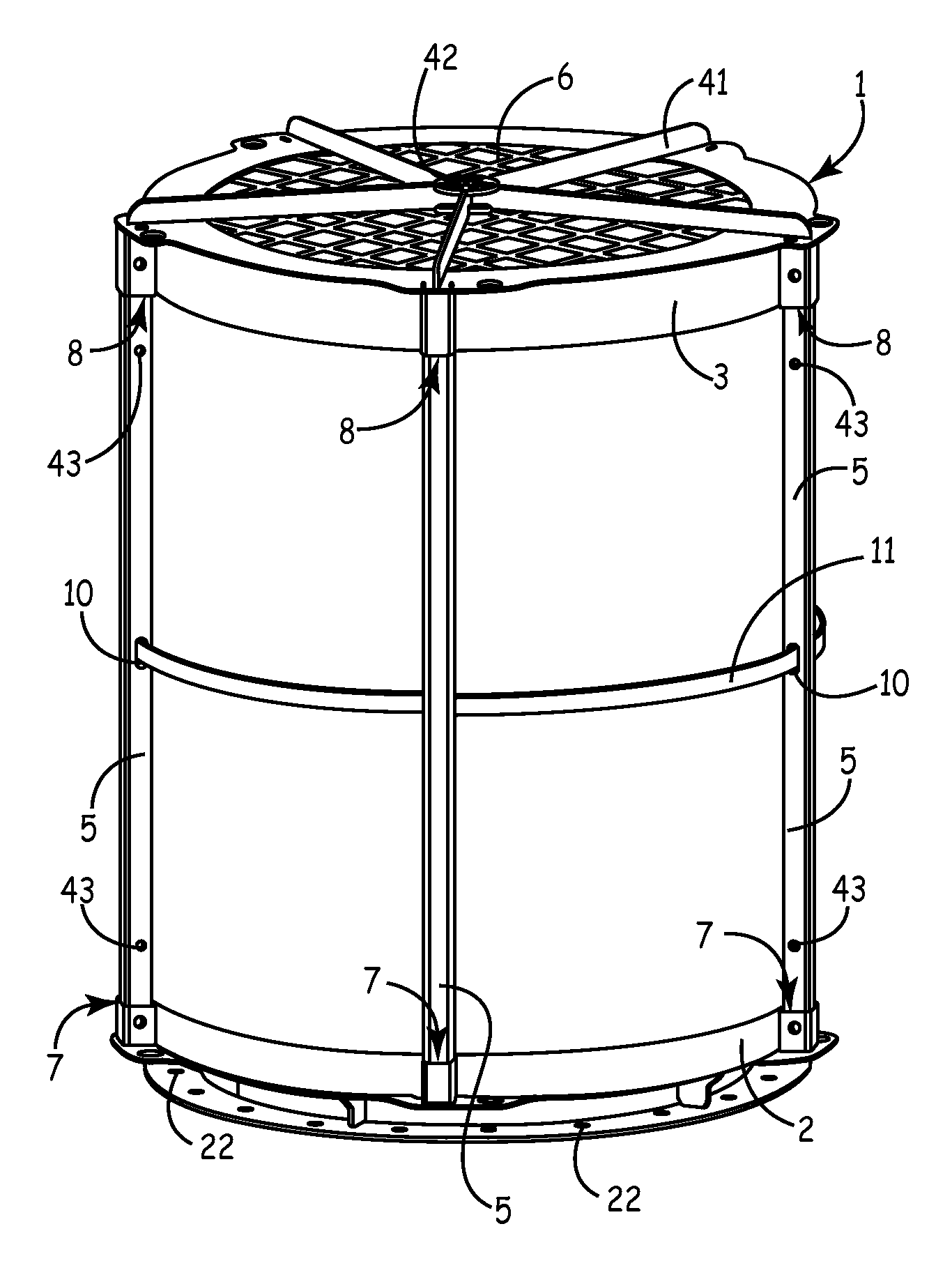
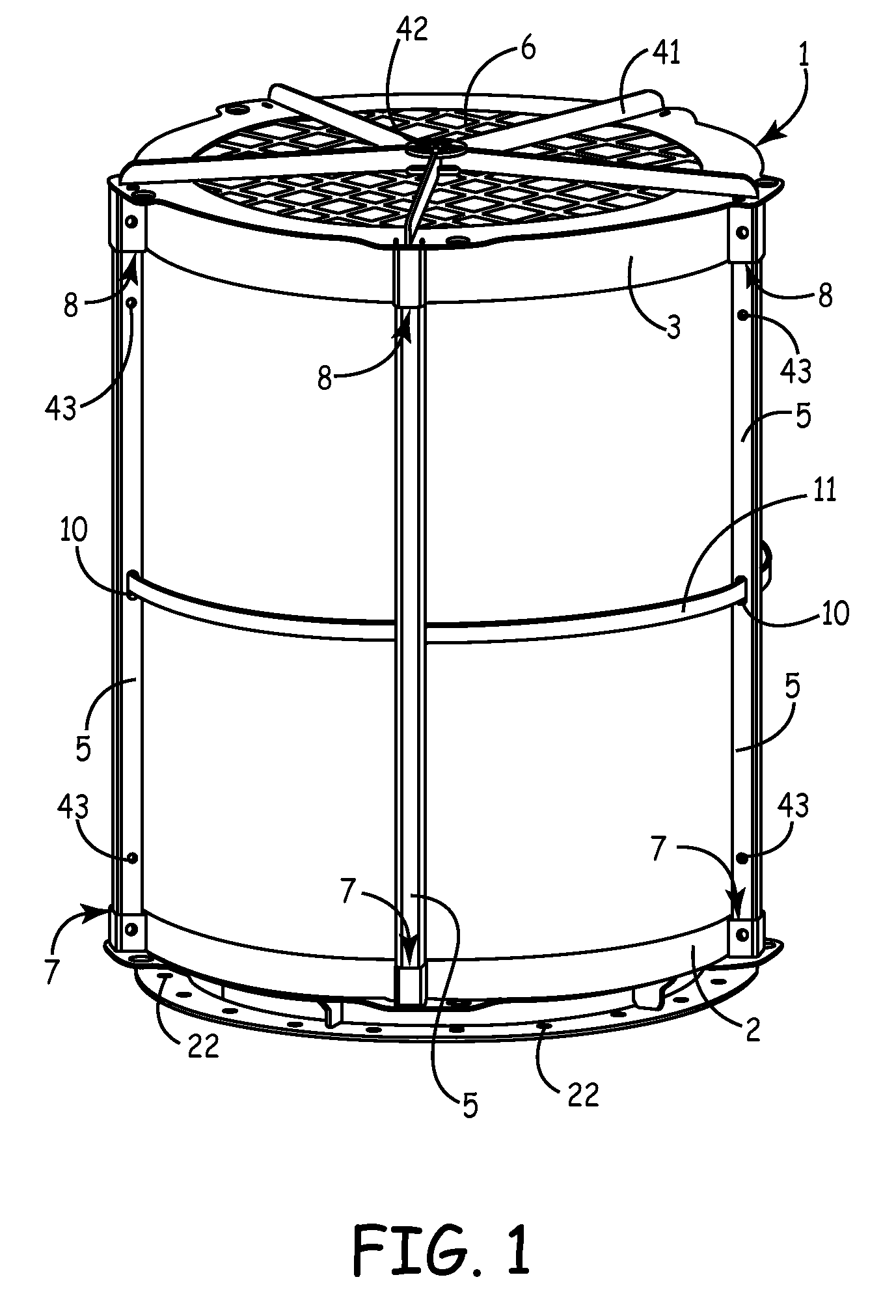
[0022]The present invention relates to an explosion pressure relief device with a wall and a framework fixing the wall. In the case of an explosion in a container to which an explosion pressure relief device is attached, such explosion pressure relief device serves to allow the pressure wave to escape at best greatly weakened and to retain a flame front and possibly dusts and to cool combustion gases. For this purpose, a pressure relief device known from the document DE 38 22 012 C2 has a wall which is composed of an undulated multi-ply layer of noble metal or comparable materials, so that a free discharge of the expansion and combustion gases leaving the container is not or only insignificantly impeded. The wall of the known explosion pressure relief device is pierced like a sieve with numerous holes, through which the radially escaping combustion gases pass approximately at right angles. Between the individual layers of noble metal or stainless steel, glass wool, rock wool or cera...


PUM


Abstract

This invention relates to an explosion pressure relief device with a wall and a framework fixing the wall. In the case of an explosion in a container to which an explosion pressure relief device is attached, such explosion pressure relief device serves to allow the pressure wave to escape at best greatly weakened.

Description

Priority[0001]This application claims the benefit of German Application Serial No. 20 2006 017 508.3 entitled “Explosion Pressure Relief Device”, filed Nov. 15, 2006, which application is hereby incorporated by reference in its entirety.BACKGROUND OF THE INVENTION[0002]In known explosion pressure relief devices the walls are held by a frame-work, which firmly accommodates the wall in itself and consists of profiled parts welded to each other. In the case of a pressure relief event performed by the explosion pressure relief device, the wall frequently is clogged by the escaping combustion and expansion gases as well as dusts, so that the pressure relief device cannot be used once again for preventing the exit of an explosion. Thus, safety against the exit of explosions only can be obtained by newly procuring an explosion pressure relief device. This involves considerable costs for the user.[0003]Therefore, a need exists for an improved explosion pressure relief device.SUMMARY OF THE ...

Claims


Application Information

Patent Timeline
Patent Type & Authority Applications(United States)
IPC IPC(8): B65D90/22F16K17/14
CPCF16K17/40B65D90/325Y10T137/1647Y10T137/1699
Inventor PENNO, STEFANPENNO, BERNHARD
Owner REMBE
Why Eureka
Try Eureka