
Method for Managing Lamella Vibrations of a Lip Channel of a Head Box and the Lamella for the Lip Channel of the Headbox

a technology of lamella and lip channel, which is applied in the direction of machine wet end, textiles and papermaking, papermaking, etc., can solve the problems of fibrous web striation and interference in flow

Inactive Publication Date: 2008-05-15
VALMET TECH INC
View PDF5 Cites 8 Cited by
  • Summary
  • Abstract
  • Description
  • Claims
  • Application Information

AI Technical Summary

Benefits of technology

"The invention is a new method to control the vibration of a lip channel's lamella in a head box, which is used in production techniques for head boxes. The method uses an active structure to manage the vibration of the lamella, which can help to reduce problems related to cockling, vibration, and production techniques. The active structure can be a piezo material, which can be used to measure and regulate the lamella's vibration, stiffness, and hardness. The method can be used in a variety of production techniques and can help to improve the quality of the finished product."

Problems solved by technology

The head box's most common problems and weak points that are caused inhomogeneously and / or irregularlyin the flow direction, and / orproceeding in a transversal lateral / vertical direction as for the flow direction from the mass flow of the mass suspension, various turbulences in the lip channel of the head box, lamellas' vibration problems, streak formation and other structure problems of the fibrous web line, such as level anomalies and blisters in the fibrous web.
It is also already common knowledge that the problem is that the vibration of the lamella used in the head box's lip channel causes striation in the fibrous web, as for example in the paper web.
Regarding yet this problem it can be noticed that the cockling of the lamella's trailing head can cause interferences in the flow that can be seen in the finished web as streaks.
In addition, the weak point of this solution is that it can work only as a basis for the planning in a chosen, restricted mass flow area.

Method used


Image

  • Method for Managing Lamella Vibrations of a Lip Channel of a Head Box and the Lamella for the Lip Channel of the Headbox
  • Method for Managing Lamella Vibrations of a Lip Channel of a Head Box and the Lamella for the Lip Channel of the Headbox
  • Method for Managing Lamella Vibrations of a Lip Channel of a Head Box and the Lamella for the Lip Channel of the Headbox

Examples


Embodiment Construction

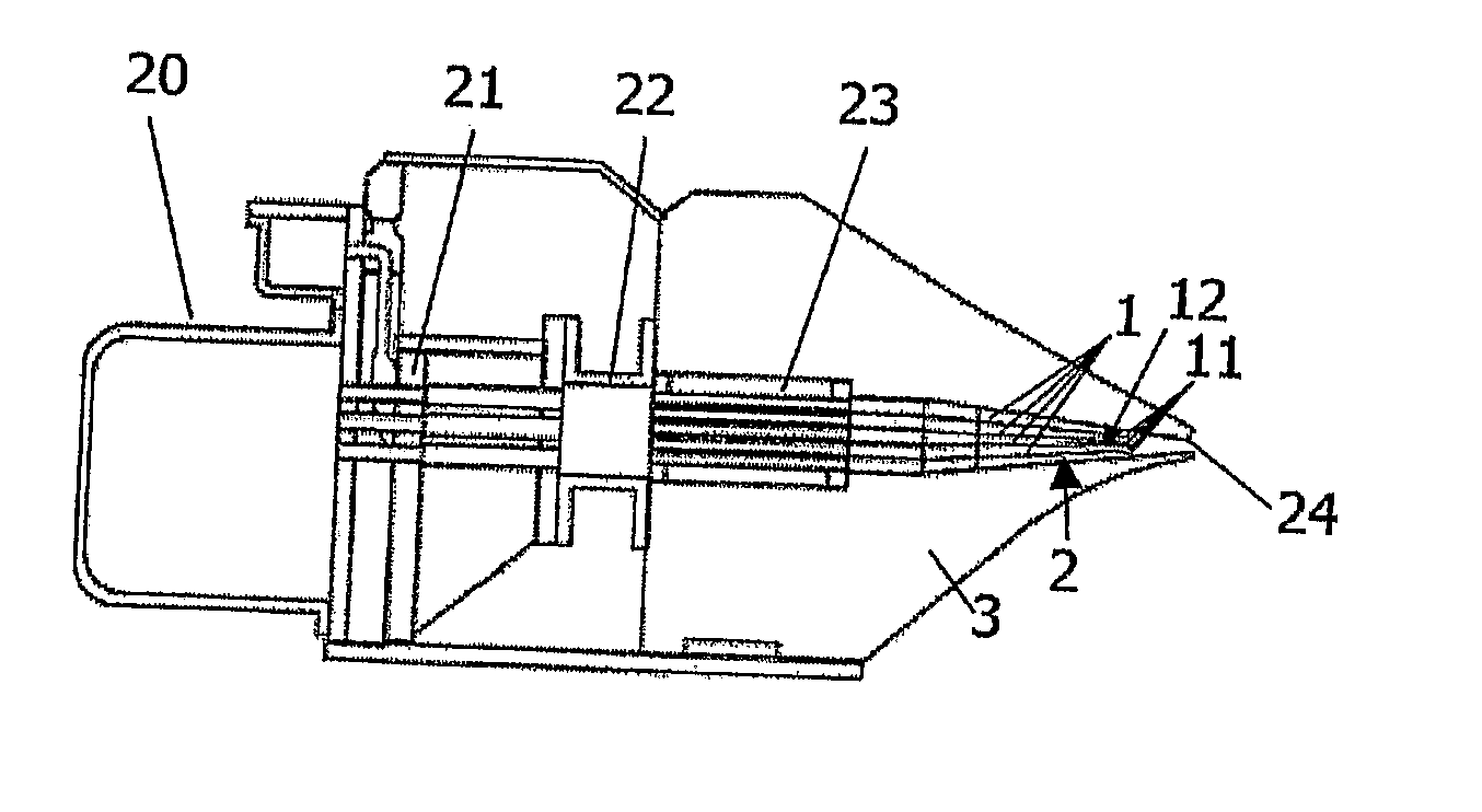
[0048]Reference is made to FIG. 1, which represents, in the direction of the mass flow, a cross-section of a head box 3. The head box consists of a manifold 20, manifold pipes 21, distributing chamber 22 and after the turbulence generator 23, a lip channel 2. At the end of the lip channel 2 in the flow direction of the mass suspension, or in the MD-direction, the head box 3 consists of the slice. Inside the lip channel there have been arranged sequentially four pieces of lamellas 1. Through lip channel 2 of the head box the single mass flows flow differentiated by the lamellas 1 and the mass flows are united after the lamella structure at the end of the lip channel. This kind of a head box is already known, and there is no need to explain other structure configuration of the head box more precisely in order to explain the invention.

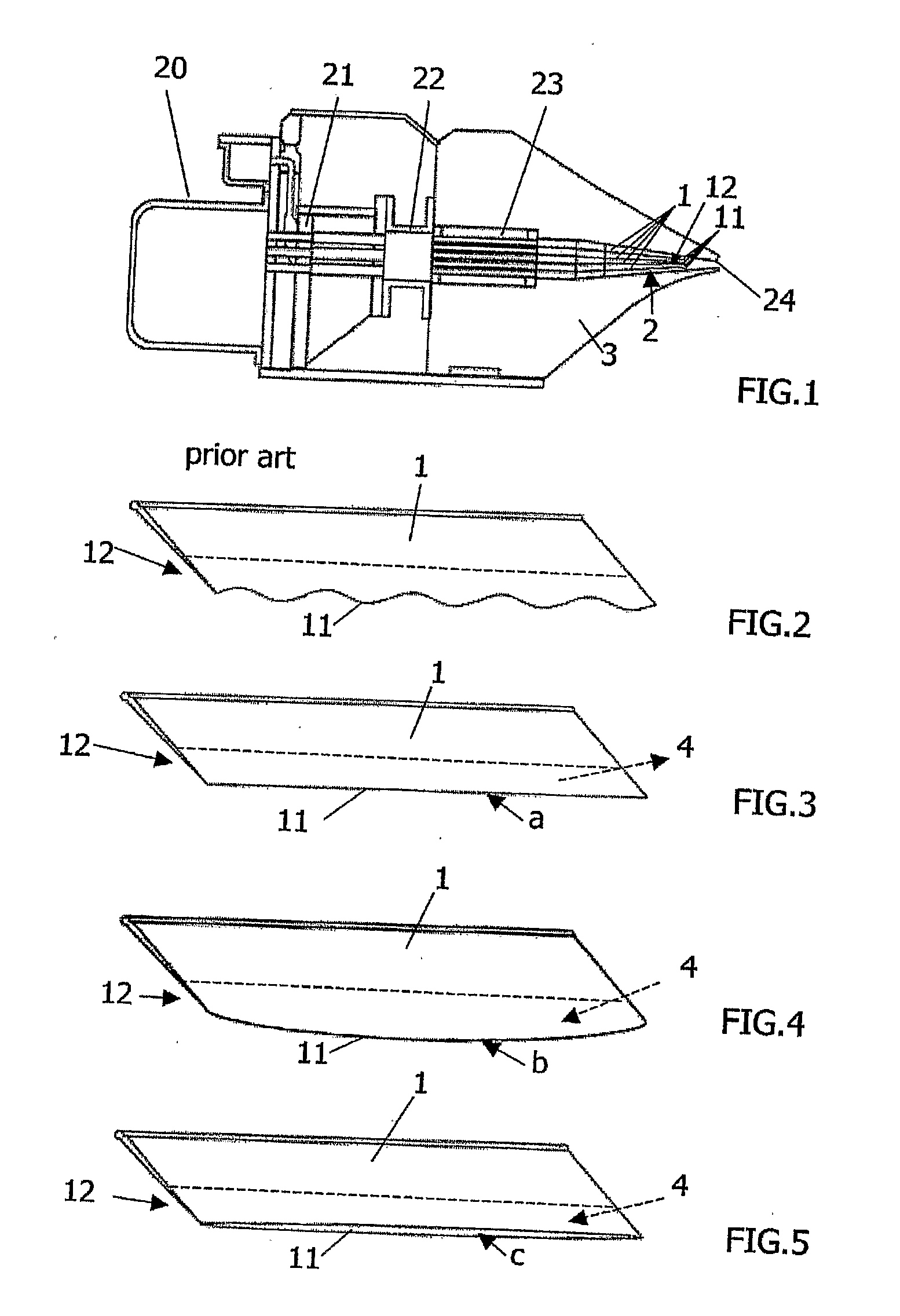
[0049]Referring to FIG. 2, where the lamella 1 is represented in accordance with the prior art, which typical weak point is that it can generate, due to ...


PUM


Abstract

A procedure and arrangement to control the lamella of a headbox's lip channel, when the mass flow goes in the headbox (3) through the lip channel (2), in which case single mass flows are held separate from each other with the lamella (1) before the flows are united after the lamella. The lamella's dimensions, mechanical characteristics and / or dynamic characteristics are changed at least in the lamella's border area with an active structure, which is active and / or passive active tool and / or active and / or passive active material.

Description

CROSS REFERENCES TO RELATED APPLICATIONS[0001]This application is a U.S. national stage application of international app. No. PCT / FI2006 / 050093, filed Mar. 8, 2006, the disclosure of which is incorporated by reference herein, and claims priority on Finnish App. No. 20050315, filed Mar. 24, 2005.STATEMENT AS TO RIGHTS TO INVENTIONS MADE UNDER FEDERALLY SPONSORED RESEARCH AND DEVELOPMENT[0002]Not applicable.BACKGROUND OF THE INVENTION[0003]The invention at hand is related to the head box of a fibrous web machine. More precisely the subject of the invention at hand is a method and an arrangement for managing a lamella vibration of a lip channel of a head box and the lamella for the lip channel of the head box.[0004]In this context, the term head box stands for a unit of a fibrous web machine, as for example a paper machine, a board machine, a pulp drying machine, a tissue machine or similar, which is used in creating mass suspension before the forming unit. The function of the head box...

Claims


Application Information

Patent Timeline
Patent Type & Authority Applications(United States)
IPC IPC(8): D21F11/00D21F1/02D21F1/06
CPCD21F1/028D21F1/02
Inventor LEPOMAKI, HANNUJETSU, PETRIHEIKKINEN, JUKKA T.PUURTINEN, ARILUMIALA, JUHANA
Owner VALMET TECH INC
Learn More