Methods and apparatuses for electronic time delay and systems including same

Inactive Publication Date: 2008-05-15
NORTHROP GRUMMAN SYST CORP
View PDF24 Cites 44 Cited by
  • Summary
  • Abstract
  • Description
  • Claims
  • Application Information

AI Technical Summary

Benefits of technology

[0011]Another embodiment of the present invention includes a method of using an electronic time delay apparatus within an explosive or propellant system. The method comprises applying an external force to an element to displace the element responsive to the external force, connecting a power sour

Problems solved by technology

Pressure balancing a well is an important procedure because failure to do so, or if the procedure is done incorrectly, may lead to equipment damage as well as possible injury to equipment operators if insufficient hydrostatic pressure is present in the casing or liner or, if too great a hydrostatic pressure is present, the producing formation exposed by the perforating operation may be contaminated or production compromised or prevented without remedial measures.
As described below in greater detail, pyrotechnic fuse-based time delay devices have reliability and accuracy concerns, as well as time limitations which may eventually lead to greater complexity and increased costs for customers of the oil tool industry.
Stringing together multiple pyrotechnic time delay devices diminishes the system's reliability and increases the system cost and complexity.

Method used


Image

  • Methods and apparatuses for electronic time delay and systems including same
  • Methods and apparatuses for electronic time delay and systems including same
  • Methods and apparatuses for electronic time delay and systems including same

Examples


Embodiment Construction

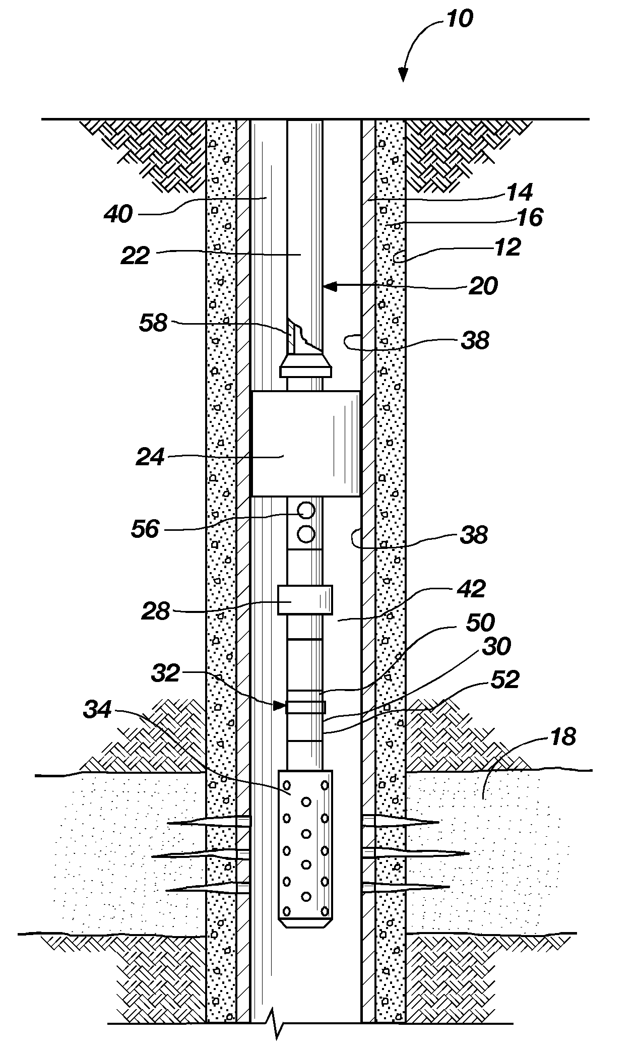
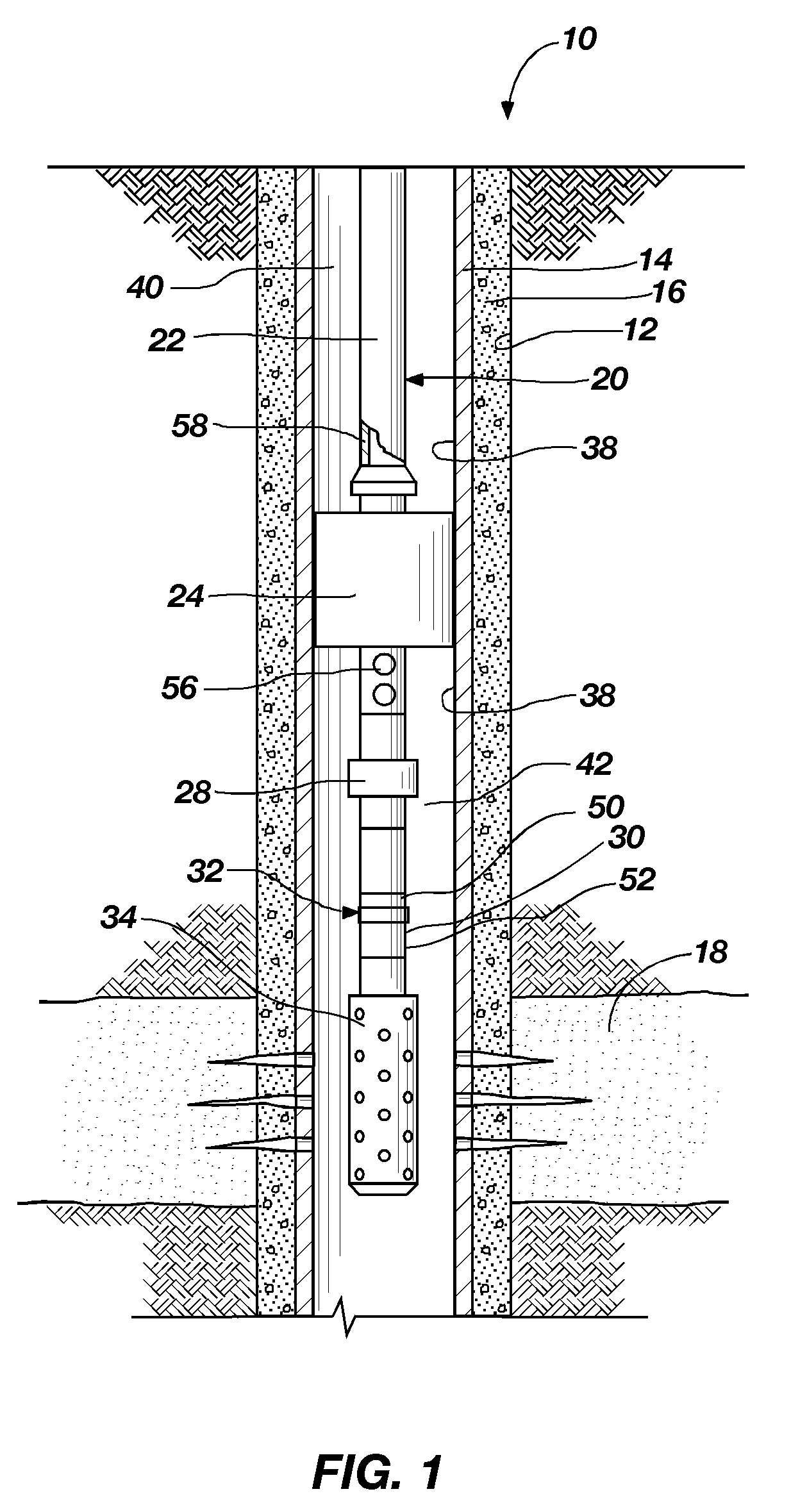
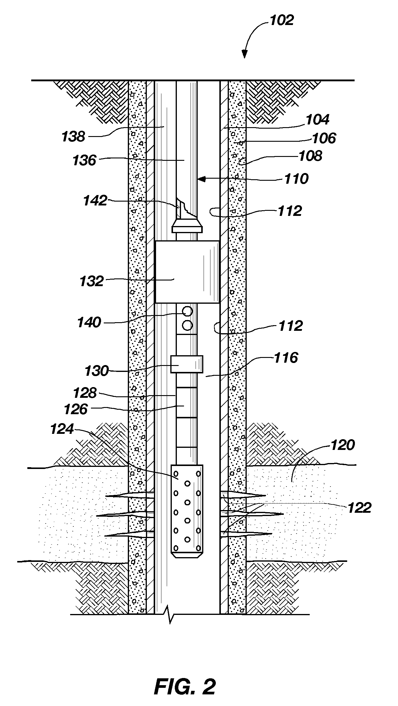
[0024]The present invention, in various embodiments, comprises apparatuses and methods of operation for an electronic time delay assembly suitable for use within an explosive or propellant system configured, by way of nonlimiting example, as a well perforating system to address the reliability concerns, as well as the cost and complexity issues associated with conventional time delay devices.

[0025]In the following description, circuits and functions may be shown in block diagram form in order not to obscure the present invention in unnecessary detail. Conversely, specific circuit implementations shown and described are examples only and should not be construed as the only way to implement the present invention unless specified otherwise herein, Additionally, block definitions and partitioning of logic between various blocks is exemplary of a specific implementation. It will be readily apparent to one of ordinary skill in the art that the present invention may be practiced by numerou...


PUM


Abstract

Electronic time delay apparatuses and methods of use are disclosed. An explosive or propellant system, which may be configured as a well perforating system includes an electronic time delay assembly comprising an input subassembly, an electronic time delay circuit, and an output subassembly. The input subassembly is activated by an external stimulus, wherein an element is displaced to activate an electronic time delay circuit. The electronic time delay circuit comprises a time delay device coupled with a voltage firing circuit. The electronic time delay circuit counts a time delay, and, upon completion, raises a voltage until a threshold firing voltage is exceeded. Upon exceeding the threshold firing voltage, a voltage trigger switch will break down to transfer energy is to an electric initiator to initiate an explosive booster within the output subassembly. The explosive booster provides the detonation output to initiate the next element explosive or propellant element, such as an array of shaped charges in the well perforating system.

Description

RELATED APPLICATIONS[0001]This application is a continuation-in-part of U.S. patent application Ser. No. 11 / 553,361 entitled METHODS AND APPARATUSES FOR ELECTRONIC TIME DELAY AND SYSTEMS INCLUDING SAME filed Oct. 26, 2006, the disclosure of which is hereby incorporated by reference.FIELD OF THE INVENTION[0002]This invention, in various embodiments, relates generally to time delay apparatuses and, more specifically, to apparatuses comprising an electronic time delay assembly suitable for use in initiating explosives and propellants, as well as systems including an electronic time delay system and methods of operation thereof.BACKGROUND OF THE INVENTION[0003]Perforating systems used for completing an oil or gas well are well known in the art. Well bores, which are drilled through earth formations for extracting hydrocarbons in the form of oil and gas, are conventionally lined by inserting a steel casing or liner into the well, and cementing at least a portion of the casing or liner in...

Claims


Application Information

Patent Timeline
IPC IPC(8): E21B29/02
CPCE21B43/1185F42C11/06F42C15/00F42D1/055F42C15/32F42C19/06F42C15/16F42B3/192
Inventor PRINZ, FRANCOIS X.ARRELL, JOHN A.BORJA, RONALD S.SLADE, WILLIAM J.
Owner NORTHROP GRUMMAN SYST CORP
Why Eureka
Try Eureka